Raspberry Pi Pico Realtime Clock with Temperature Monitoring
Realtime Clock & Temperature Monitoring using RPI Pico on ST7735 LCD Display
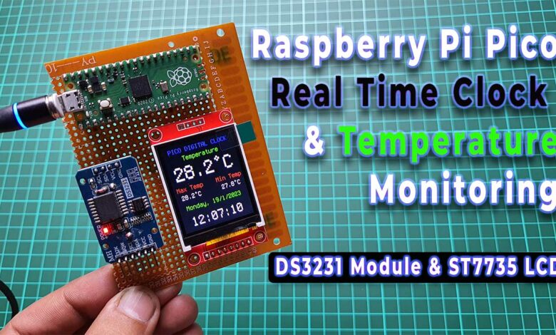
In this project, we will build a Raspberry Pi Pico Realtime Clock with a Temperature Monitoring system using a 1.8-inch ST7735 TFT LCD display, and a DS3231 RTC module. We will be programming the Raspberry Pi Pico board using CircuitPython. This project is suitable for anyone who wants to learn more about using Raspberry Pi Pico, CircuitPython, and electronics.
- Overview: Pico Realtime Clock with Temperature
- Components Required
- Interfacing DS3231 RTC Module & 1.8 inch ST7735 LCD Display with Raspberry Pi Pico
- Project PCB Gerber File & PCB Ordering Online
- Installing CircuitPython on Raspberry Pi Pico
- Program Source/Code & Library Files
- Project Demonstration
- Conclusion
Overview: Pico Realtime Clock with Temperature
The Raspberry Pi Pico is a powerful microcontroller that can be used for a variety of projects. And when combined with a real-time clock module, it can be used to keep track of time even when the power is off. In this project, we’ll be using the DS3231 RTC module and the 1.8-inch TFT LCD display to create a real-time clock with a temperature monitoring system.
The DS3231 RTC module is a real-time clock module that can keep track of time even when the power is off. It’s accurate and reliable, and it communicates with the Raspberry Pi Pico using I2C. It also comes with a built-in Digital Temperature Sensor which has an accuracy of ±3°C.
The ST7735 display is a small 1.8-inch TFT LCD color display that can be used to display graphics and text. In this project, we’ll be using it to display the current temperature, maximum and minimum temperature of the day, date, and Time.
- Getting Started with Raspberry Pi Pico using MicroPython
- Interface BME280 with Raspberry Pi Pico using MicroPython
- RFID Based Door Lock Control System using Raspberry Pi Pico
- Read Internal Temperature Sensor Value from Raspberry Pi Pico
- Internet Clock Using NodeMCU ESP8266 and 16×2 LCD without RTC Module
- Capacitive Soil Moisture Sensor with Raspberry Pi Pico
Components Required
To build Raspberry Pi Pico Realtime Clock with Temperature Monitoring System, we’ll need a PCB or breadboard, some jumper wires, and a few components. You can easily purchase the components from the links provided below.
| S.N | COMPONENTS NAME | QUANTITY | PURCHASE LINKS |
|---|---|---|---|
| 1 | Raspberry Pi Pico Board | 1 | Amazon | AliExpress |
| 2 | 1.8" ST7735 TFT LCD Display | 1 | Amazon | AliExpress |
| 3 | DS3231 RTC Module | 5 | Amazon | AliExpress |
| 4 | Breadboard | 1 | Amazon | AliExpress |
| 5 | Jumper Cables | 20 | Amazon | AliExpress |
Interfacing DS3231 RTC Module & 1.8 inch ST7735 LCD Display with Raspberry Pi Pico
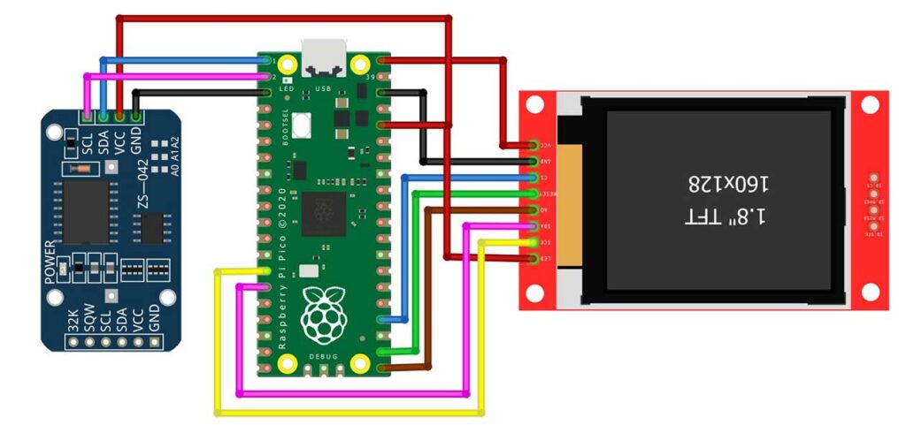
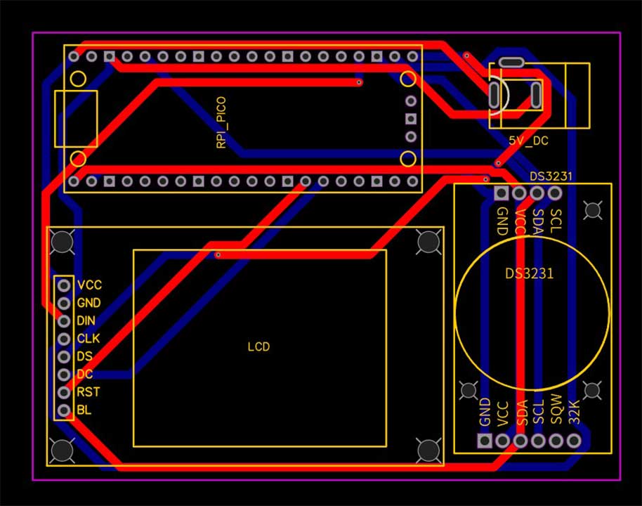
Let’s start by connecting the display to the Raspberry Pi Pico. Vcc goes to Vbus, GND to a GND pin, CS to pin GP18, Reset to pin GP17, A0 to pin GP16, SDA to pin GP11, SCK to pin GP10, and LED to 3.3Volt output. Next, connect the DS3231 real-time clock module to the Raspberry Pi Pico by connecting the ground pin to the Pi’s ground, the Vcc pin to the 3.3Volt pin, the SDA pin to the pin GP0, and SCL pin to analog pin GP01.
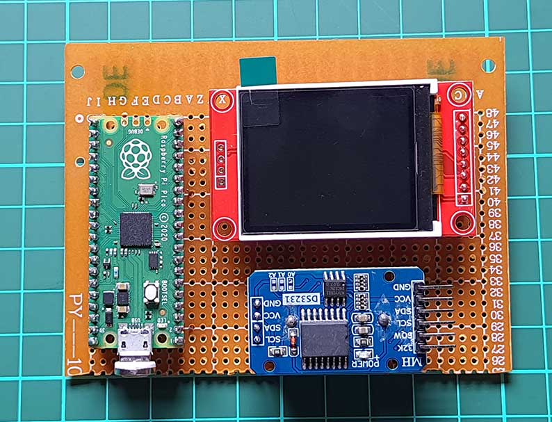
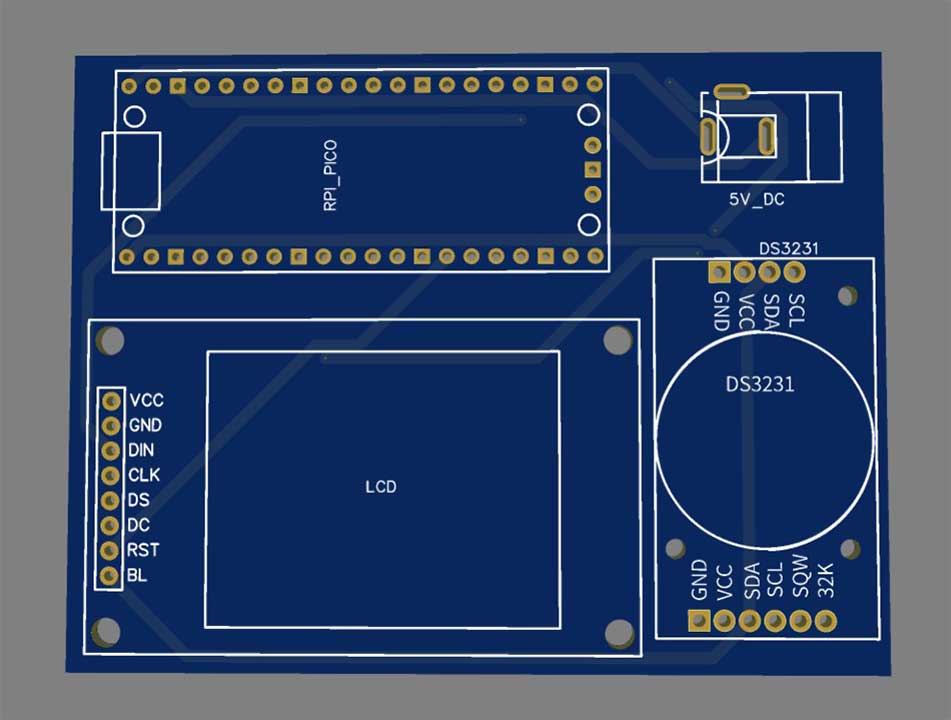
I have connected the Raspberry Pi Pico, the TFT LCD display, and the DS3231 RTC module to the zero PCB board. You can use the custom PCB designed for this project or a breadboard connection for testing purposes.
Project PCB Gerber File & PCB Ordering Online
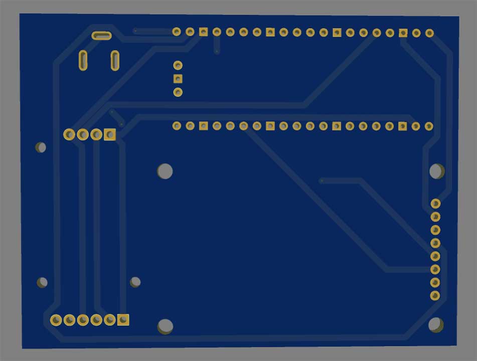
To implement this whole system you will need a PCB. You can use breadboard assembly just to test this project. So, to make your work easier I have designed a custom PCB for this project. You can directly order your PCB from PCBWay.com.
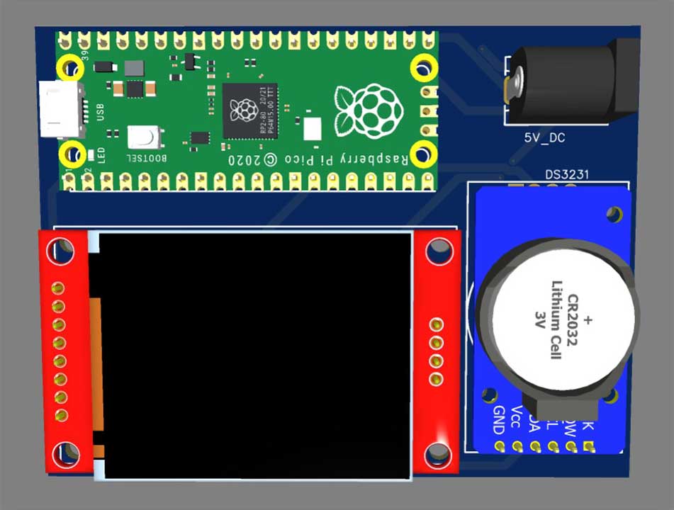
Now you can visit the PCBWay official website by clicking here: PCBWay.com. So you will be directed to the PCBWay website.

You can now upload the Gerber File to the Website and place an order. The PCB quality is superb & high standard. That is why most people trust PCBWay for PCB & PCBA Services. PCBWay is a leading manufacturer of high-quality PCBs and offers a wide range of services, including PCB fabrication, assembly, and components sourcing.
With everything connected, it’s time to write the code that will make our project work. We’ll be using CircuitPython to write the code.
Installing CircuitPython on Raspberry Pi Pico
To program the Raspberry Pi Pico using CircuitPython, we need to install CircuitPython on the board. To do this, we need to download the latest CircuitPython.uf2 file for the Raspberry Pi Pico from the CircuitPython website.
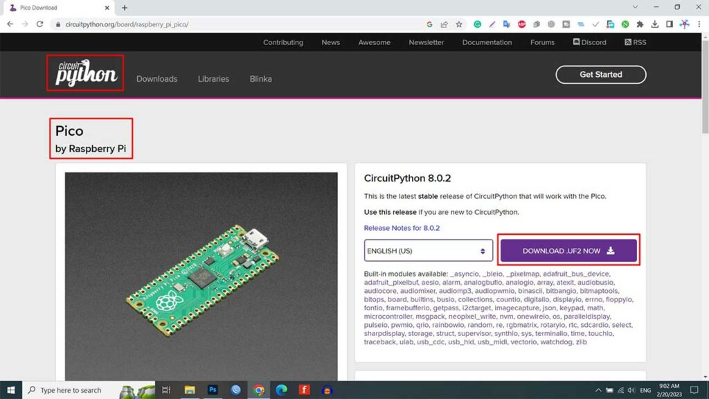
Once downloaded, we need to hold down the BOOTSEL button on the Raspberry Pi Pico. while plugging it into our computer. This will cause the Raspberry Pi Pico to appear as a USB drive named RPI. We then need to drag and drop the CircuitPython.uf2 file onto the RPI drive. This will install CircuitPython on the Raspberry Pi Pico.
Program Source/Code & Library Files
To use the ST7735 Display and DS3231 RTC module, we need to install some libraries. These libraries can be downloaded from below.

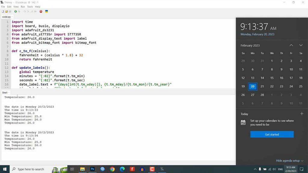
Once downloaded, extract all the files and copy all the files and library folders to the CIRCUITPY drive. Also, replace this code.py file with a new one. Now open this code.py in Thonny IDE.
import time
import board, busio, displayio
import adafruit_ds3231
from adafruit_st7735r import ST7735R
from adafruit_display_text import label
from adafruit_bitmap_font import bitmap_font

def c_to_f(celsius):
    fahrenheit = (celsius * 1.8) + 32
    return fahrenheit

def update_labels():
    global temperature
    minutes = "{:02}".format(t.tm_min)
    seconds = "{:02}".format(t.tm_sec)
    date_label.text = f"{days[int(t.tm_wday)]}, {t.tm_mday}/{t.tm_mon}/{t.tm_year}"
    time_label.text = f"{t.tm_hour}:{minutes}:{seconds}"
    temperature = round(rtc.force_temperature_conversion(),1)
    temperature_string = f"{temperature}°C"
    if not metric:
        temperature = round(c_to_f(temperature),1)
        temperature_string = f"{temperature}°F"

    temperature_value_label.text = temperature_string

    set_min_max_temperature()

    if metric:
        max_temperature_value_label.text = f"{str(max_temperature)}°C"
        min_temperature_value_label.text = f"{str(min_temperature)}°C"
    else:
        max_temperature_value_label.text = f"{str(max_temperature)}°F"
        min_temperature_value_label.text = f"{str(min_temperature)}°F"

    print(f"The date is {days[int(t.tm_wday)]} {t.tm_mday}/{t.tm_mon}/{t.tm_year}")
    print("The time is {}:{:02}:{:02}".format(t.tm_hour, t.tm_min, t.tm_sec))
    print(f"Temperature: {temperature}")
    print(f"Min Temperature: {min_temperature}")
    print(f"Max Temperature: {max_temperature}")
    print(f"Temperature: {temperature}nn")

def set_min_max_temperature():
    global min_temperature, max_temperature
    if temperature > max_temperature:
        max_temperature = temperature
    if temperature < min_temperature:
        min_temperature = temperature

mosi_pin, clk_pin, reset_pin, cs_pin, dc_pin = board.GP11, board.GP10, board.GP17, board.GP18, board.GP16
days = ("Sunday", "Monday", "Tuesday", "Wednesday", "Thursday", "Friday", "Saturday")

i2c = busio.I2C(board.GP1, board.GP0)
rtc = adafruit_ds3231.DS3231(i2c)

metric = True # Set to False for degrees Fahrenheit

# UNCOMMENT THE FOLLOWING THREE LINES THE FIRST TIME YOU RUN THE CODE TO SET THE TIME!
#set_time = time.struct_time((2023, 2, 19, 12, 29, 20, 8, -1, -1)) # Year, Month, Date, Hour, Minutes, Seconds, Week Day
#print("Setting time to:", set_time)
#rtc.datetime = set_time

# Comment out the above three lines again after setting the time!

displayio.release_displays()
spi = busio.SPI(clock=clk_pin, MOSI=mosi_pin)
display_bus = displayio.FourWire(spi, command=dc_pin, chip_select=cs_pin, reset=reset_pin)

t = rtc.datetime

min_temperature = 100.0
max_temperature = 0.0
temperature = 0

font_file = "fonts/terminal.bdf"
font = bitmap_font.load_font(font_file)

display = ST7735R(display_bus, width=128, height=160, bgr = True)

ui = displayio.Group()
display.show(ui)

# Create date label
date_label = label.Label(font, color=0x00FF00, text = "Date")
date_label.anchor_point = (0.5, 0.0)
date_label.anchored_position = (64, 110)

# Create time label
time_label = label.Label(font, color=0xFFFFFF)
time_label.anchor_point = (0.5, 0.0)
time_label.anchored_position = (64, 130)
time_label.scale = (2)

clock_label = label.Label(font, color=0x0000FF, text = "PICO DIGITAL CLOCK")
clock_label.anchor_point = (0.5, 0.0)
clock_label.anchored_position = (64, 5)

# Create temperature label
temperature_label = label.Label(font, color=0x00FF00, text = "Temperature")
temperature_label.anchor_point = (0.5, 0.0)
temperature_label.anchored_position = (64, 20)

# Create max_temperature label
max_temperature_label = label.Label(font, color=0xFF0000, text = "Max Temp")
max_temperature_label.anchor_point = (0.0, 0.0)
max_temperature_label.anchored_position = (5, 75)

# Create min_temperature label
min_temperature_label = label.Label(font, color=0xFF0000, text = "Min Temp")
min_temperature_label.anchor_point = (1.0, 0.0)
min_temperature_label.anchored_position = (125, 75)

# Create temperature value label
temperature_value_label = label.Label(font, color=0xFFFFFF)
temperature_value_label.anchor_point = (0.5, 0.0)
temperature_value_label.anchored_position = (64, 35)
temperature_value_label.scale = (3)

# Create max_temperature value label
max_temperature_value_label = label.Label(font, color=0xFFFFFF)
max_temperature_value_label.anchor_point = (0.0, 0.0)
max_temperature_value_label.anchored_position = (10, 90)

# Create min_temperature value label
min_temperature_value_label = label.Label(font, color=0xFFFFFF)
min_temperature_value_label.anchor_point = (1.0, 0.0)
min_temperature_value_label.anchored_position = (120, 90)

ui.append(clock_label)
ui.append(min_temperature_value_label)
ui.append(max_temperature_value_label)
ui.append(time_label)
ui.append(date_label)
ui.append(temperature_value_label)
ui.append(max_temperature_label)
ui.append(min_temperature_label)
ui.append(temperature_label)

while True:
    t = rtc.datetime
    update_labels()
    time.sleep(1)  # wait a second
code.py explanation
This is a CircuitPython code for a device that displays the date, time, and temperature. It imports various libraries such as:
- Time
- Board
- Busio
- Displayio
- Adafruit_ds3231
- Adafruit_st7735r
- Adafruit_display_text and
- Adafruit_bitmap_font
import time
import board, busio, displayio
import adafruit_ds3231
from adafruit_st7735r import ST7735R
from adafruit_display_text import label
from adafruit_bitmap_font import bitmap_font
The program uses a DS3231 RTC (real-time clock) module to keep track of the date and time. It also has functions to convert Celsius to Fahrenheit and update labels for displaying the information on a 128×160 pixel ST7735R display. The temperature can be displayed in either Celsius or Fahrenheit, and the program keeps track of the minimum and maximum temperature readings.
def c_to_f(celsius):
    fahrenheit = (celsius * 1.8) + 32
    return fahrenheit

def update_labels():
    global temperature
    minutes = "{:02}".format(t.tm_min)
    seconds = "{:02}".format(t.tm_sec)
    date_label.text = f"{days[int(t.tm_wday)]}, {t.tm_mday}/{t.tm_mon}/{t.tm_year}"
    time_label.text = f"{t.tm_hour}:{minutes}:{seconds}"
    temperature = round(rtc.force_temperature_conversion(),1)
    temperature_string = f"{temperature}°C"
    if not metric:
        temperature = round(c_to_f(temperature),1)
        temperature_string = f"{temperature}°F"

    temperature_value_label.text = temperature_string

    set_min_max_temperature()

    if metric:
        max_temperature_value_label.text = f"{str(max_temperature)}°C"
        min_temperature_value_label.text = f"{str(min_temperature)}°C"
    else:
        max_temperature_value_label.text = f"{str(max_temperature)}°F"
        min_temperature_value_label.text = f"{str(min_temperature)}°F"

    print(f"The date is {days[int(t.tm_wday)]} {t.tm_mday}/{t.tm_mon}/{t.tm_year}")
    print("The time is {}:{:02}:{:02}".format(t.tm_hour, t.tm_min, t.tm_sec))
    print(f"Temperature: {temperature}")
    print(f"Min Temperature: {min_temperature}")
    print(f"Max Temperature: {max_temperature}")
    print(f"Temperature: {temperature}nn")
The labels for date, time, and temperature are displayed using bitmap fonts, and the color of the font can be customized. The temperature is displayed in larger font sizes, and the minimum and maximum temperatures are displayed in smaller font sizes.
font_file = "fonts/terminal.bdf"
font = bitmap_font.load_font(font_file)

display = ST7735R(display_bus, width=128, height=160, bgr = True)

ui = displayio.Group()
display.show(ui)

# Create date label
date_label = label.Label(font, color=0x00FF00, text = "Date")
date_label.anchor_point = (0.5, 0.0)
date_label.anchored_position = (64, 110)

# Create time label
time_label = label.Label(font, color=0xFFFFFF)
time_label.anchor_point = (0.5, 0.0)
time_label.anchored_position = (64, 130)
time_label.scale = (2)

clock_label = label.Label(font, color=0x0000FF, text = "PICO DIGITAL CLOCK")
clock_label.anchor_point = (0.5, 0.0)
clock_label.anchored_position = (64, 5)

# Create temperature label
temperature_label = label.Label(font, color=0x00FF00, text = "Temperature")
temperature_label.anchor_point = (0.5, 0.0)
temperature_label.anchored_position = (64, 20)

# Create max_temperature label
max_temperature_label = label.Label(font, color=0xFF0000, text = "Max Temp")
max_temperature_label.anchor_point = (0.0, 0.0)
max_temperature_label.anchored_position = (5, 75)

# Create min_temperature label
min_temperature_label = label.Label(font, color=0xFF0000, text = "Min Temp")
min_temperature_label.anchor_point = (1.0, 0.0)
min_temperature_label.anchored_position = (125, 75)

# Create temperature value label
temperature_value_label = label.Label(font, color=0xFFFFFF)
temperature_value_label.anchor_point = (0.5, 0.0)
temperature_value_label.anchored_position = (64, 35)
temperature_value_label.scale = (3)

# Create max_temperature value label
max_temperature_value_label = label.Label(font, color=0xFFFFFF)
max_temperature_value_label.anchor_point = (0.0, 0.0)
max_temperature_value_label.anchored_position = (10, 90)

# Create min_temperature value label
min_temperature_value_label = label.Label(font, color=0xFFFFFF)
min_temperature_value_label.anchor_point = (1.0, 0.0)
min_temperature_value_label.anchored_position = (120, 90)

ui.append(clock_label)
ui.append(min_temperature_value_label)
ui.append(max_temperature_value_label)
ui.append(time_label)
ui.append(date_label)
ui.append(temperature_value_label)
ui.append(max_temperature_label)
ui.append(min_temperature_label)
ui.append(temperature_label)
We need to uncomment these lines to set the time on the RTC module. We then need to comment on these lines again and run the code. This will display the current date, time, and temperature on the ST7735 Display.
# UNCOMMENT THE FOLLOWING THREE LINES THE FIRST TIME YOU RUN THE CODE TO SET THE TIME!
#set_time = time.struct_time((2023, 2, 19, 12, 29, 20, 1, -1, -1)) # Year, Month, Date, Hour, Minutes, Seconds, Week Day
#print("Setting time to:", set_time)
#rtc.datetime = set_time

# Comment out the above three lines again after setting the time!
Overall, this program can be used to create a simple and compact device for displaying date, time, and temperature information.
Project Demonstration
Once the code is uploaded to the Raspberry Pi Pico, we can see the Real-Time Clock with Temperature Display in action.
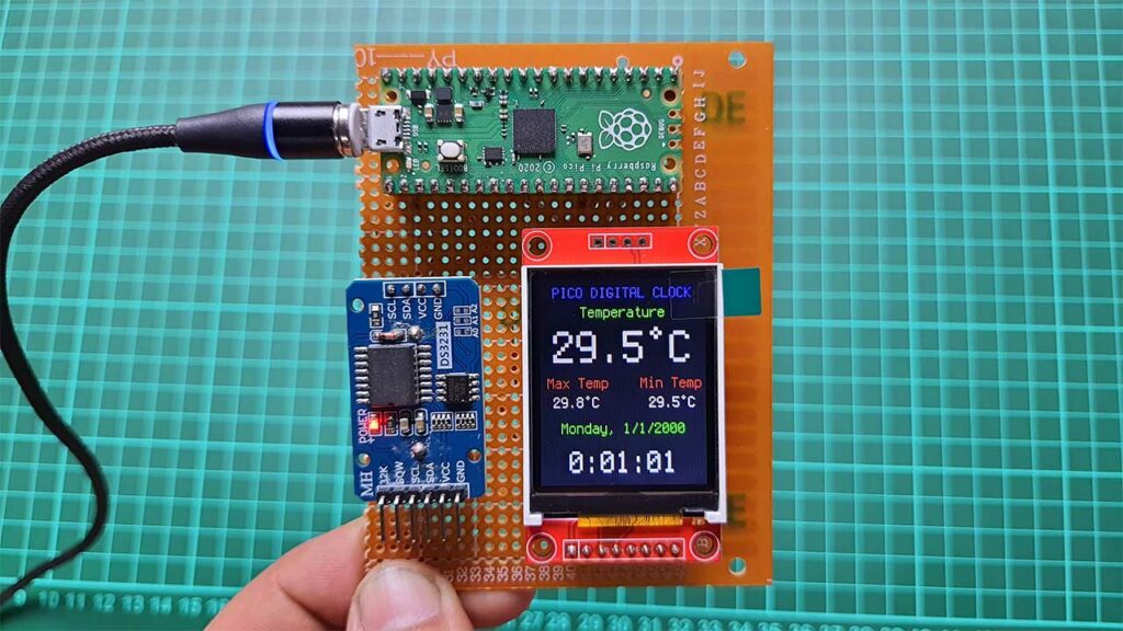
The 1.8-inch ST7735 TFT LCD Display will show the current date, time, and temperature. The temperature sensor will measure the ambient temperature and display it on the screen. The Real-Time Clock will keep track of the time even if the Raspberry Pi Pico is disconnected from power. This makes it useful for projects that require accurate timekeeping.
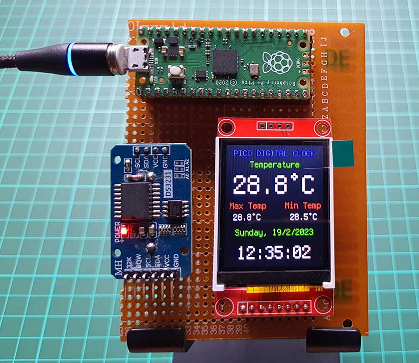
You can customize the code to change the display format or add additional features to the project.
Conclusion
In this project, we have built Raspberry Pi Pico Realtime Clock with Temperature Monitoring using a 1.8-inch ST7735 TFT LCD Display and a DS3231 RTC module. We have used CircuitPython to program the Raspberry Pi Pico, making it easy to write code and develop projects without the need for complicated software.
Basically, we have also installed the required libraries and font files and edited the code.py file to display the current date, time, and temperature on the ST7735 Display. With the help of PCBWay.com, we have been able to create a high-quality PCB for this project. We hope this project has inspired you to start working with Raspberry Pi Pico and CircuitPython and to create your own innovative projects.

When I disconnect power on reconnect it goes to the time when the power was disconnected
Hello, thank you for the easy to follow instructions to make this project. However, the day wouldn’t change for me, it only displays Friday even when I change the week day. Please help. Thanks!