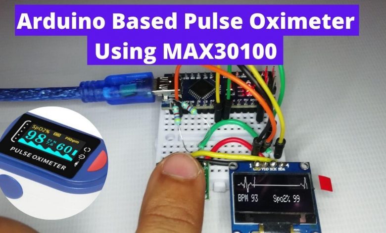
Overview: Pulse Oximeter using Arduino
Nowadays, we can see many pulse oximeter sensors available in the market. We used it for measuring the heart rate and Sp02 level. So, today we will make Pulse Oximeter using Arduino, MAX30100, and 0.96″ SSD1306 OLED Display to display output. we want this project to be compact, so here we are using the Arduino Nano microcontroller. we want the device to be more compact and smaller in size. It can be handy in this pandemic situation.
This compact Pulse oximeter device is similar to the device that we find within the market. However, we do not recommend you to use this device for medical purposes to evaluate patient’s conditions. this is only for educational and learning purposes.
Components Required
The Components Required to make Pulse Oximeter using Arduino & MAX30100 are listed below. You can buy them directly from the Amazon link provided.
| S.N | Components Name | Description | Quantity | |
|---|---|---|---|---|
| 1 | Arduino Nano | Arduino Nano R3 | 1 | https://amzn.to/3vN4ZHu |
| 2 | MAX30100 Oximeter Sensor | MAX30100 Heart Rate Oximeter Sensor Arduino Module | 1 | https://amzn.to/3hdjkt2 |
| 3 | OLED Display | 0.96" I2C OLED Display | 1 | https://amzn.to/32WRubSv |
| 4 | 4.7K Ohm 1/4 Watt Resistor | 4.7K Ohm Resistor | 2 | https://amzn.to/3urSdhv |
| 5 | Jumper Wires | Jumper Cables breadboard friendly | 20 | https://amzn.to/3vw9ZAt |
| 6 | Breadboard | Mini Breadboard | 1 | https://amzn.to/2NP2UKL |
MAX30100 Oximeter Sensor
Before getting into the project, let’s introduce the main component of this project. The MAX30100 sensor is a simple module that communicates in the I2C interface with the microcontroller. It provides the SpO2 and pulse information to the connected microcontroller. In simple terms, this sensor is used for identifying oxygen saturation. Hence, this module can be used for monitoring the pulse rate and oxygen saturation level of the blood in a non-invasive form.
It uses photodetectors and optical elements where IR LED modulates the LED pulses. we can configure the LED current from 0 to 50mA. We have provided the image of the MAX30100 sensor below.
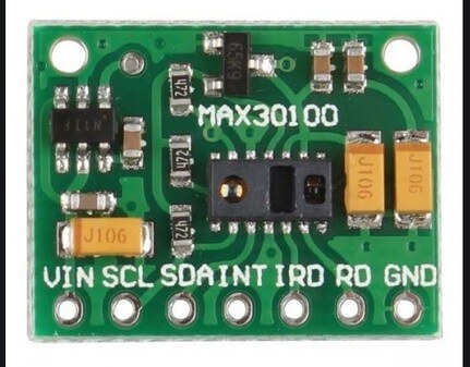
This pulse oximeter sensor works between 1.8v – 5.5v power supply. For this project, we are using 0.96 Inch I2C based OLED display. it’s a 128×64 Resolution display with an SSD1306 Chip.
0.96″ SSD1306 OLED Display
The OLED display that we’ll use in this project is the 0.96-inch SSD1306 mode with 128×64 pixels as shown in the following figure.
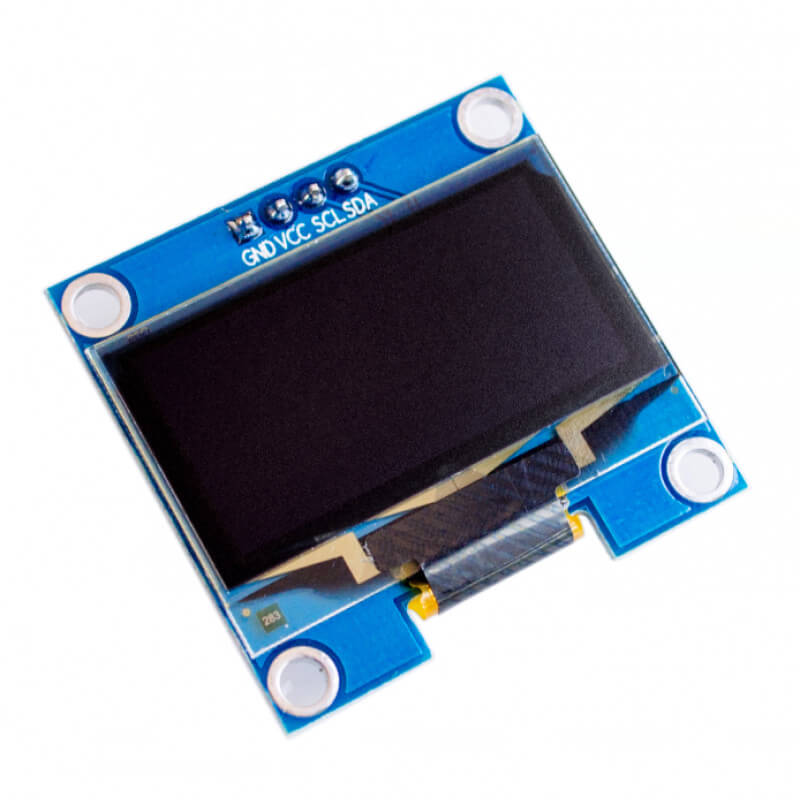
The OLED display doesn’t require a backlight, due to which there is a very nice contrast in dark environments. Additionally, it consumes less power when compared to other displays. The display we’re using has four pins. It works with an I2C communication protocol.
Schematic of the Arduino Pulse Oximeter
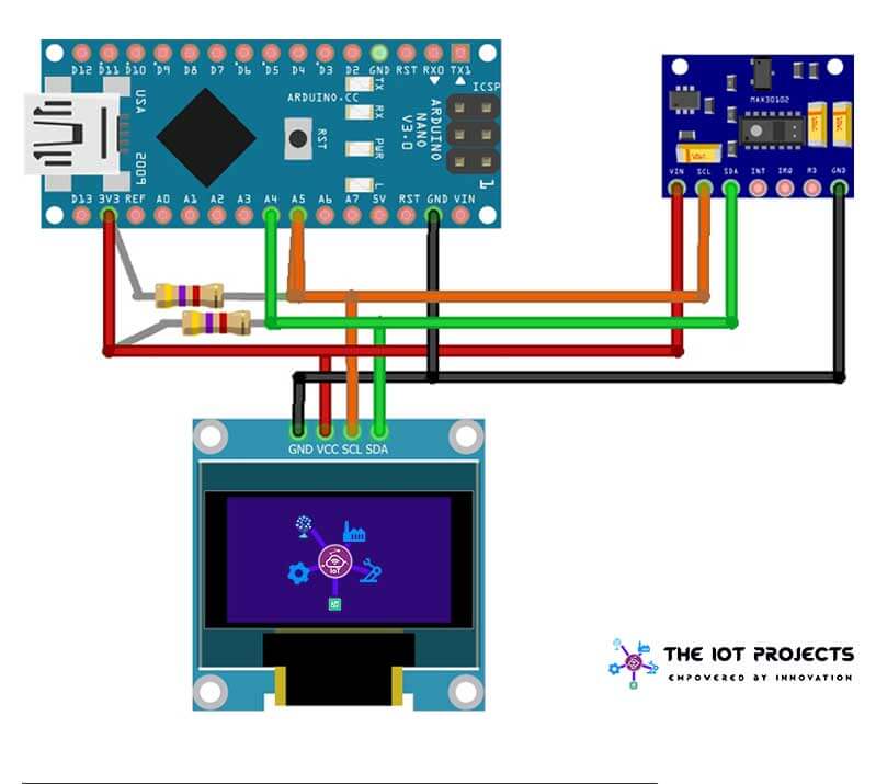
This is a really simple schematic. We connect the I2C pin (SCL & SDA) of both the MAX30100 sensor and OLED Display to the A5 and A4 pins of the Arduino Nano using a pull-up resistor of 4.7k value. Similarly, the Vcc pin connected to 3.3V and GND to the Ground pin respectively.
Explore More:
- IoT Based Patient Health Monitoring System Using ESP8266/ESP32 Web Server
- BMP280 Based Weather Station using Arduino and OLED Display
- How 555 IC works in Astable Operation & Monostable Operation
- Interface DHT11 Sensor with Arduino and LCD
- BMP280 Based IoT Weather Station using ESP8266 & OLED Display
PCB Designing for Arduino Pulse Oximeter
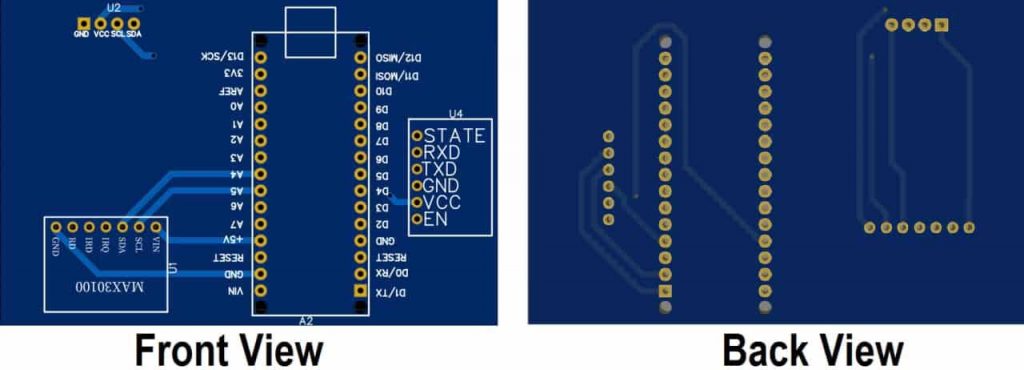
The PCB for Arduino Pulse Oximeter has been designed in the online PCB-making tool EasyEDA. Below are the front view and Back View of the PCB.
You can download the Gerber file and order the PCB online from PCBWay.
Now you can visit https://www.PCBWAY.com/ and order the PCB. PCBWay is one of the biggest PCB manufacturer companies in China. They offer very good quality PCB at a cheap price.

The PCB quality from PCBWay.com is good and excellent. So many people trust them for PCB & PCBA Services because of their quality.
Arduino based Oximeter Program Code
This is the program code for Pulse Oximeter using Arduino & MAX30100 Sensor. We have used some important libraries in the code. You need to install them in your Arduino IDE. The “MAX30100_PulseOximeter.h” is used to read the data from the sensor. Wire.h for I2C communication. Similarly, Adafruit_GFX.h for showing animation on the display. Lastly, Adafruit_SSD1306.h is for the display driver. These all libraries are included at the beginning of the code.
#include <Wire.h>
#include "MAX30100_PulseOximeter.h"
#include <Adafruit_GFX.h>
#include <Adafruit_SSD1306.h>
Next, we defined ENABLE_MAX30100 which is used for setting the MAX30100 enable bit as 1. Similarly, SCREEN_WIDTH and SCREEN_HEIGHT are for OLED Display resolution.
#define ENABLE_MAX30100 1
#define SCREEN_WIDTH 128 // OLED display width, in pixels
#define SCREEN_HEIGHT 32 //64 // OLED display height, in pixels
We defined a “onBeatDetected” callback function. The function is called when the pulse is detected by the sensor.
void onBeatDetected()
{
  Serial.println("Beat!");
  heart_beat(&xPos);
}
First, we Activated the display driver for I2C Communication. Then clear the display, set the size, color, and position of the text. Finally, Print “Pulse Oximeter” on OLED Display.
/ SSD1306_SWITCHCAPVCC = generate display voltage from 3.3V internally
  if (!display.begin(SSD1306_SWITCHCAPVCC, SCREEN_ADDRESS)) {
    Serial.println(F("SSD1306 allocation failed"));
    for (;;); // Don't proceed, loop forever
  }
display.clearDisplay();
  display.setTextSize(1);
  display.setTextColor(WHITE);
  display.setCursor(20, 18);
display.print("Pulse OxiMeter");
Here, we have initialize the MAX30100 sensor and setup the the Heartbeat animation location:
#if ENABLE_MAX30100
  // Initialize the Pulse oximeter instance
  // Failures are generally because of an improper I2C wiring, missing power supply
  // or wrong target chip
  if (!pox.begin()) {
    Serial.println("FAILED");
    for (;;);
  } else {
    Serial.println("SUCCESS");
  }
Setting up the Oximeter MAX30100 sensor LED Current and setting the “onBeatDetected” callback function:
pox.setIRLedCurrent(MAX30100_LED_CURR_7_6MA);
  // Register a callback for the beat detection
  pox.setOnBeatDetectedCallback(onBeatDetected);
By calling this function on the loop section, we can get the updated BPM and SPO2 value from the sensor.
pox.getHeartRate(); and pox.getSpO2();
Final Program Code
This is the Final Program code for Pulse Oximeter using Arduino & MAX30100 project. You can simply copy and paste it into your Arduino IDE. Install all the required libraries from the library manager then upload it to your Arduino Nano board by selecting Correct board and Its COM Port.
#include <Wire.h>
#include "MAX30100_PulseOximeter.h"
#include <Adafruit_GFX.h>
#include <Adafruit_SSD1306.h>
#define ENABLE_MAX30100 1
#define SCREEN_WIDTH 128 // OLED display width, in pixels
#define SCREEN_HEIGHT 32 //64 // OLED display height, in pixels
// Declaration for an SSD1306 display connected to I2C (SDA, SCL pins)
// The pins for I2C are defined by the Wire-library.
// On an arduino UNO:       A4(SDA), A5(SCL)
// On an arduino MEGA 2560: 20(SDA), 21(SCL)
// On an arduino LEONARDO:   2(SDA),  3(SCL), ...
#define OLED_RESET     -1 // 4 // Reset pin # (or -1 if sharing Arduino reset pin)
#define SCREEN_ADDRESS 0x3c ///< See datasheet for Address; 0x3D for 128x64, 0x3C for 128x32
Adafruit_SSD1306 display(SCREEN_WIDTH, SCREEN_HEIGHT, &Wire, OLED_RESET);
#if ENABLE_MAX30100
#define REPORTING_PERIOD_MS     5000
// PulseOximeter is the higher level interface to the sensor
// it offers:
//  * beat detection reporting
//  * heart rate calculation
//  * SpO2 (oxidation level) calculation
PulseOximeter pox;
#endif
uint32_t tsLastReport = 0;
int xPos = 0;
// Callback (registered below) fired when a pulse is detected
void onBeatDetected()
{
  Serial.println("Beat!");
  heart_beat(&xPos);
}
void setup()
{
  Serial.begin(115200);
  Serial.println("SSD1306 128x64 OLED TEST");
  // SSD1306_SWITCHCAPVCC = generate display voltage from 3.3V internally
  if (!display.begin(SSD1306_SWITCHCAPVCC, SCREEN_ADDRESS)) {
    Serial.println(F("SSD1306 allocation failed"));
    for (;;); // Don't proceed, loop forever
  }
  // Show initial display buffer contents on the screen --
  // the library initializes this with an Adafruit splash screen.
  //display.display();
  display.clearDisplay();
  display.setTextSize(1);
  display.setTextColor(WHITE);
  display.setCursor(20, 18);
  // Display static text
  display.print("Pulse OxiMeter");
  int temp1 = 0;
  int temp2 = 40;
  int temp3 = 80;
  heart_beat(&temp1);
  heart_beat(&temp2);
  heart_beat(&temp3);
  xPos = 0;
  display.display();
  delay(2000); // Pause for 2 seconds
  display.cp437(true);
  display.clearDisplay();
  Serial.print("Initializing pulse oximeter..");
#if ENABLE_MAX30100
  // Initialize the PulseOximeter instance
  // Failures are generally due to an improper I2C wiring, missing power supply
  // or wrong target chip
  if (!pox.begin()) {
    Serial.println("FAILED");
    for (;;);
  } else {
    Serial.println("SUCCESS");
  }
  // The default current for the IR LED is 50mA and it could be changed
  //   by uncommenting the following line. Check MAX30100_Registers.h for all the
  //   available options.
  pox.setIRLedCurrent(MAX30100_LED_CURR_7_6MA);
  // Register a callback for the beat detection
  pox.setOnBeatDetectedCallback(onBeatDetected);
  display_data(0, 0);
#endif
}
void loop()
{
#if ENABLE_MAX30100
  // Make sure to call update as fast as possible
  pox.update();
  int bpm = 0;
  int spo2 = 0;
  // Asynchronously dump heart rate and oxidation levels to the serial
  // For both, a value of 0 means "invalid"
  if (millis() - tsLastReport > REPORTING_PERIOD_MS) {
    //Serial.print("Heart rate:");
    bpm = pox.getHeartRate();
    spo2 = pox.getSpO2();
    Serial.println(bpm);
    //Serial.print("bpm / SpO2:");
    Serial.println(spo2);
    //Serial.println("%");
    tsLastReport = millis();
    display_data(bpm, spo2);
  }
#endif
  drawLine(&xPos);
}
void display_data(int bpm, int spo2) {
  display.fillRect(0, 18, 127, 15, SSD1306_BLACK);
  display.setTextSize(1);
  display.setTextColor(WHITE);
  display.setCursor(0, 18);
  // Display static text
  display.print("BPM ");
  display.print(bpm);
  display.display();
  display.setTextSize(1);
  display.setTextColor(WHITE);
  display.setCursor(64, 18);
  // Display static text
  display.print("Spo2% ");
  display.println(spo2);
  display.display();
}
void drawLine(int *x_pos) {
  // Draw a single pixel in white
  display.drawPixel(*x_pos, 8, SSD1306_WHITE);
  display.drawPixel((*x_pos)++, 8, SSD1306_WHITE);
  display.drawPixel((*x_pos)++, 8, SSD1306_WHITE);
  display.drawPixel((*x_pos)++, 8, SSD1306_WHITE);
  display.drawPixel((*x_pos), 8, BLACK);  // -----
  //Serial.println(*x_pos);
  display.fillRect(*x_pos, 0, 31, 16, SSD1306_BLACK);
  display.display();
  delay(1);
  if (*x_pos >= SCREEN_WIDTH) {
    *x_pos = 0;
  }
}
void heart_beat(int *x_pos) {
  /************************************************/
  //display.clearDisplay();
  display.fillRect(*x_pos, 0, 30, 15, SSD1306_BLACK);
  // Draw a single pixel in white
  display.drawPixel(*x_pos + 0, 8, SSD1306_WHITE);
  display.drawPixel(*x_pos + 1, 8, SSD1306_WHITE);
  display.drawPixel(*x_pos + 2, 8, SSD1306_WHITE);
  display.drawPixel(*x_pos + 3, 8, SSD1306_WHITE);
  display.drawPixel(*x_pos + 4, 8, BLACK); // -----
  //display.display();
  //delay(1);
  display.drawPixel(*x_pos + 5, 7, SSD1306_WHITE);
  display.drawPixel(*x_pos + 6, 6, SSD1306_WHITE);
  display.drawPixel(*x_pos + 7, 7, SSD1306_WHITE); // .~.
  //display.display();
  //delay(1);
  display.drawPixel(*x_pos + 8, 8, SSD1306_WHITE);
  display.drawPixel(*x_pos + 9, 8, SSD1306_WHITE); // --
  //display.display();
  //delay(1);
  /******************************************/
  display.drawPixel(*x_pos + 10, 8, SSD1306_WHITE);
  display.drawPixel(*x_pos + 10, 9, SSD1306_WHITE);
  display.drawPixel(*x_pos + 11, 10, SSD1306_WHITE);
  display.drawPixel(*x_pos + 11, 11, SSD1306_WHITE);
  //display.display();
  //delay(1);
  /******************************************/
  display.drawPixel(*x_pos + 12, 10, SSD1306_WHITE);
  display.drawPixel(*x_pos + 12, 9, SSD1306_WHITE);
  display.drawPixel(*x_pos + 12, 8, SSD1306_WHITE);
  display.drawPixel(*x_pos + 12, 7, SSD1306_WHITE);
  //display.display();
  //delay(1);
  display.drawPixel(*x_pos + 13, 6, SSD1306_WHITE);
  display.drawPixel(*x_pos + 13, 5, SSD1306_WHITE);
  display.drawPixel(*x_pos + 13, 4, SSD1306_WHITE);
  display.drawPixel(*x_pos + 13, 3, SSD1306_WHITE);
  //display.display();
  //delay(1);
  display.drawPixel(*x_pos + 14, 2, SSD1306_WHITE);
  display.drawPixel(*x_pos + 14, 1, SSD1306_WHITE);
  display.drawPixel(*x_pos + 14, 0, SSD1306_WHITE);
  display.drawPixel(*x_pos + 14, 0, SSD1306_WHITE);
  //display.display();
  //delay(1);
  /******************************************/
  display.drawPixel(*x_pos + 15, 0, SSD1306_WHITE);
  display.drawPixel(*x_pos + 15, 1, SSD1306_WHITE);
  display.drawPixel(*x_pos + 15, 2, SSD1306_WHITE);
  display.drawPixel(*x_pos + 15, 3, SSD1306_WHITE);
  //display.display();
  //delay(1);
  display.drawPixel(*x_pos + 15, 4, SSD1306_WHITE);
  display.drawPixel(*x_pos + 15, 5, SSD1306_WHITE);
  display.drawPixel(*x_pos + 16, 6, SSD1306_WHITE);
  display.drawPixel(*x_pos + 16, 7, SSD1306_WHITE);
  //display.display();
  //delay(1);
  display.drawPixel(*x_pos + 16, 8, SSD1306_WHITE);
  display.drawPixel(*x_pos + 16, 9, SSD1306_WHITE);
  display.drawPixel(*x_pos + 16, 10, SSD1306_WHITE);
  display.drawPixel(*x_pos + 16, 11, SSD1306_WHITE);
  //display.display();
  //delay(1);
  display.drawPixel(*x_pos + 17, 12, SSD1306_WHITE);
  display.drawPixel(*x_pos + 17, 13, SSD1306_WHITE);
  display.drawPixel(*x_pos + 17, 14, SSD1306_WHITE);
  display.drawPixel(*x_pos + 17, 15, SSD1306_WHITE);
  //display.display();
  //delay(1);
  display.drawPixel(*x_pos + 18, 15, SSD1306_WHITE);
  display.drawPixel(*x_pos + 18, 14, SSD1306_WHITE);
  display.drawPixel(*x_pos + 18, 13, SSD1306_WHITE);
  display.drawPixel(*x_pos + 18, 12, SSD1306_WHITE);
  //display.display();
  //delay(1);
  display.drawPixel(*x_pos + 19, 11, SSD1306_WHITE);
  display.drawPixel(*x_pos + 19, 10, SSD1306_WHITE);
  display.drawPixel(*x_pos + 19, 9, SSD1306_WHITE);
  display.drawPixel(*x_pos + 19, 8, SSD1306_WHITE);
  //display.display();
  //delay(1);
  /****************************************************/
  display.drawPixel(*x_pos + 20, 8, SSD1306_WHITE);
  display.drawPixel(*x_pos + 21, 8, SSD1306_WHITE);
  //display.display();
  //delay(1);
  /****************************************************/
  display.drawPixel(*x_pos + 22, 7, SSD1306_WHITE);
  display.drawPixel(*x_pos + 23, 6, SSD1306_WHITE);
  display.drawPixel(*x_pos + 24, 6, SSD1306_WHITE);
  display.drawPixel(*x_pos + 25, 7, SSD1306_WHITE);
  //display.display();
  //delay(1);
  /************************************************/
  display.drawPixel(*x_pos + 26, 8, SSD1306_WHITE);
  display.drawPixel(*x_pos + 27, 8, SSD1306_WHITE);
  display.drawPixel(*x_pos + 28, 8, SSD1306_WHITE);
  display.drawPixel(*x_pos + 29, 8, SSD1306_WHITE);
  display.drawPixel(*x_pos + 30, 8, SSD1306_WHITE); // -----
  *x_pos = *x_pos + 30;
  display.display();
  delay(1);
}
IoT Based Bidirectional Visitor Counter using ESP8266 & Blynk
Testing Arduino Based Pulse Oximeter using MAX30100
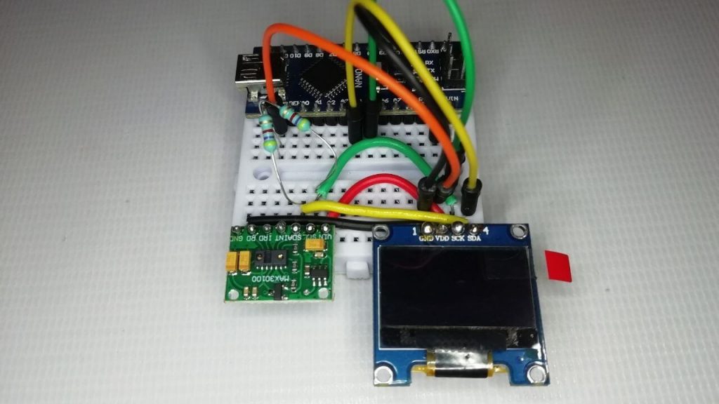
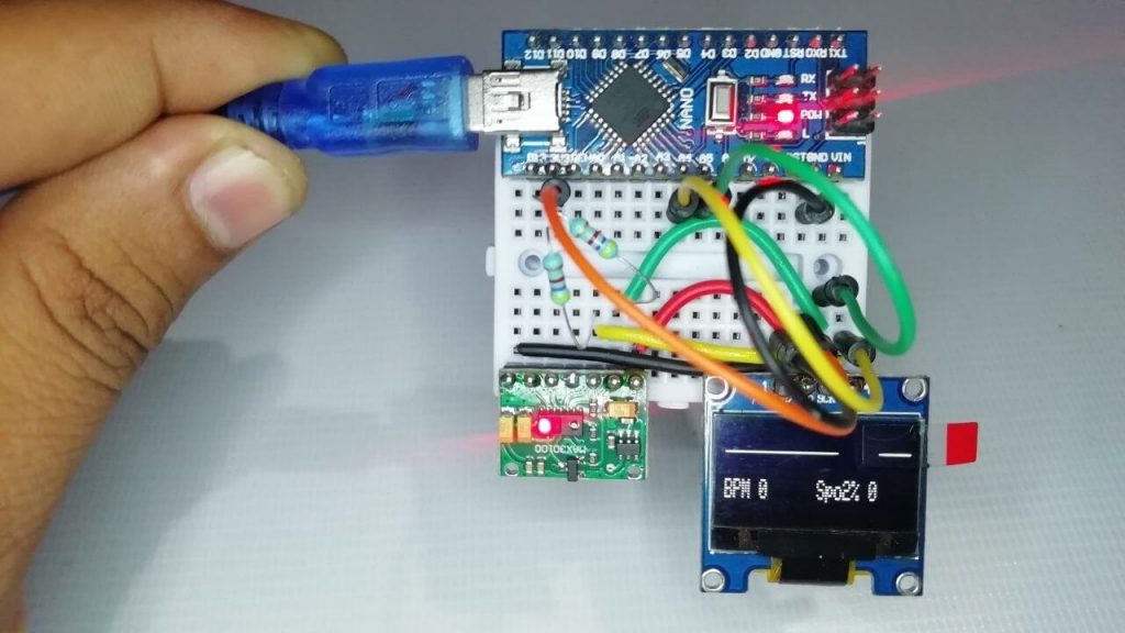
After, successful upload of the program. It’s time to test our freshly build We made Pulse Oximeter using Arduino. the circuit is assembled on a small breadboard. It perfectly displays the data on the display. When there is no data, the OLED screen looks like this.
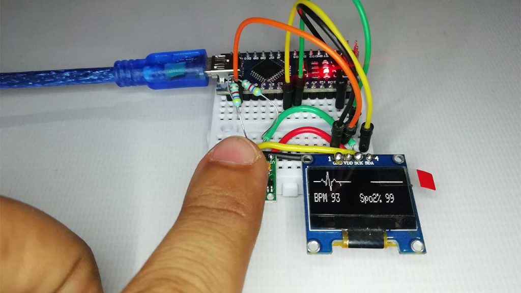
As we can see in the below image, The Heartbeat is 93 bits per minute and the SPO2 level shows 99%. The animation gets changes when the MAX30100 Pulse sensor detects heartbeats.
Video Tutorial & Guide
Need Help? Comment down below.

please can we add the Glucose mesure part to this part
if the answer yes : how?
That library doesn’t work