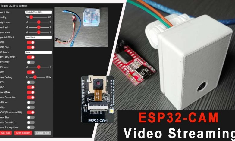
Overview: ESP32 CAM WebServer
In this project, we will program the ESP32 CAM using Arduino IDE and Stream video over Wi-Fi. The ESP32 CAM is a small and cheapest camera module that costs around $10. It comes with an ESP32-S chip which has built-in wifi and Bluetooth. Above the OV2640 camera MicroSD card slot is provided which comes in handy to store images taken with this camera.
In this tutorial, we will use an FTDI Module to program this ESP32 CAM board. Besides, we will go through its features, pins description, and set up Arduino IDE for the ESP32 Camera Module. Then we will use the ESP32 Camera webserver example code from Arduino IDE to stream video over Wi-Fi.
This is a basic tutorial to get started with ESP32 CAM. We will use the same basic project to make a smart doorbell and surveillance camera. Apart from these, we can also do face recognition-based projects for security applications.
Components Required
Following is the list of the components for Programming ESP32 CAM to Stream Video Over Wi-Fi. You can purchase all the components online from Amazon.
| S.N | Components Name | Quantity | |
|---|---|---|---|
| 1 | ESP32 CAM Board | 1 | https://amzn.to/2V5rHxD |
| 2 | FTDI Module | 1 | https://amzn.to/3zzU06q |
| 3 | Female - Female Jumper Wires | 5 | https://amzn.to/3kVFP7q |
| 4 | USB Cable | 1 | https://amzn.to/3eY5jx8 |
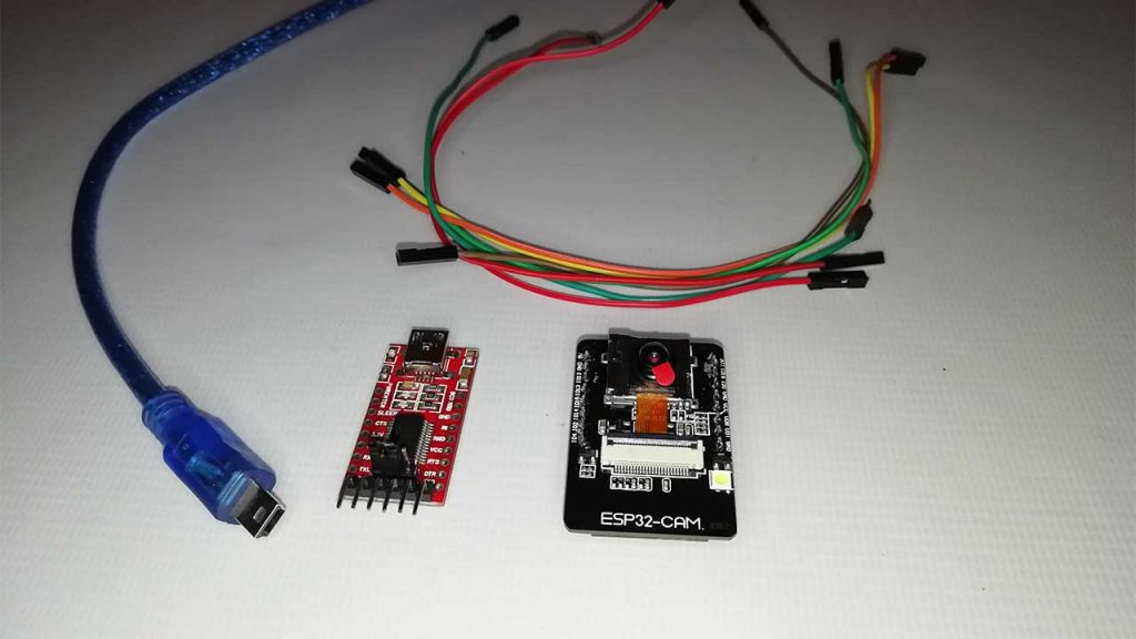
What is ESP32-CAM?
The ESP32-CAM is a small camera module with the ESP32-S chip. The module has an OV2640 camera. It also has many GPIOs for external connections. The ESP32-CAM module has been developed by so many manufacturers but the board developed by AI-Thinker is the most popular.
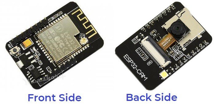
The Module is based on a 32-bit CPU controller with a frequency of 240MHz. It has a built-in 520 KB SRAM and external 4M PSRAM. This is a combined 802.11b/g/n Wi-Fi + Bluetooth/BLE SOC module. This ESP32 CAM module comes with an onboard voltage regulator.
Unfortunately, it has a single reset button at the bottom that makes the module breadboard unfriendly. You will not have access to this button if you place it on a breadboard. It also comes with an LED that can be used as a flash LED through program code modification.
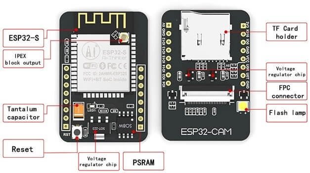
In the back of this module, you can see the PCB antenna. This module has already an antenna attached. But if you want to use good power and a good range of external antenna, you can connect one antenna to an IPX connector. In order to use that antenna, you need to connect a jumper or zero-ohm resistor to the PCB near the antenna.
OV2460 Camera
The camera module is the most important part of ESP32 CAM. We can use the OV2640 camera module having 24 pins. It has the camera resolution of up to 1600×1200 pixels.
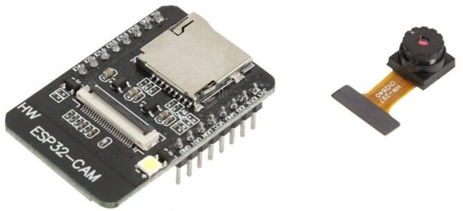
The gold-plated 24 pin connector strip lets you connect this camera with ESP32. Simply push the little slide in the opposite direction then you can observe the pins for connecting the camera. Insert the camera-facing gold-plated pins downside and then pull the slide. After successfully inserting the camera into this module it is ready to use.
SD Card Support
On the other side, there is an SD Card Holder which supports a microSD card up to 4GB. But you can even use up to 16GB SD Card with no issues.
SD card is used for storing the capture images. For demonstration purposes, I am using a 4GB microSD card. To use the SD card in your project simply insert the SD card into the SD card adaptor.
ESP32 CAM GPIO Pins
The GPIOs pins of ESP32 CAM support UART, SPI, I2C, PWM, ADC, and DAC. There are 3.3V pin, VCC pin, and 5V Pin for powering this module. We can see multiple GND Pins as well.
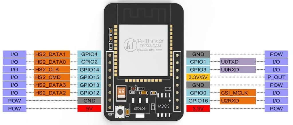
The following pins are internally connected to the microSD card reader:
GPIO 14: CLK
GPIO 15: CMD
GPIO 2: Data 0
GPIO 4: Data 1 (also connected to the on-board LED)
GPIO 12: Data 2
GPIO 13: Data 3
ESP32-CAM and FTDI Connection
To program the ESP32 CAM board, you need USB-to-TTL Converter Module or an FTDI Module. We can find so many FTDI Modules available based on CP2102 or CP2104 Chip or any other chip.
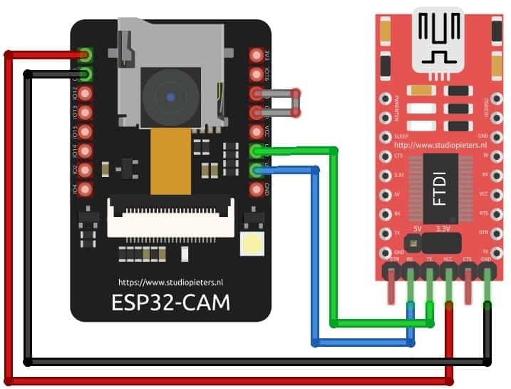
To Program ESP32 CAM and Stream Video Over Wi-Fi, make the following connection between the ESP32 CAM module and FTDI Module.
| ESP32-CAM | FTDI PROGRAMMER |
| GND | GND |
| 5V | VCC (5V) |
| U0R | TX |
| U0T | RX |
| GPIO 0 | GND |
Connect the 5V & GND Pin of FTDI module to 5V & GND of ESP32 CAM. Similarly, connect the Rx to UOT and Tx to UOR Pin. And the most important thing, you need to short the IO0 and GND Pin together. This put your ESP32 CAm into programming Mode. Once programming is done, you can remove it.
Project PCB Gerber File & PCB Ordering Online
As I have already mentioned the module is not fully breadboarded friendly. So, I designed the PCB Board for ESP32 CAM Board using EasyEDA. The PCB looks something like this.
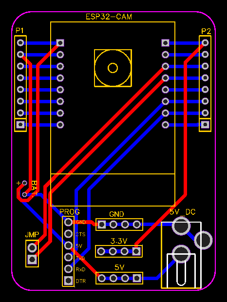
I gave the Gerber File for the PCB below. You can simply download the Gerber File and order the PCB from https://www.PCBWay.com/
Now you can visit the PCBWay official website by clicking here: https://www.pcbway.com/. So it will direct you to the PCBWay website.
You can now upload the Gerber File to the Website and place an order. The PCB quality is superb & high. That is why most people trust PCBWay for PCB & PCBA Services.
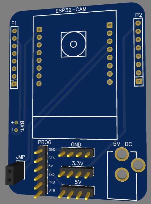
Now you can assemble the components on the PCB Board.
Setting Up ESP32 CAM Board on Arduino IDE
To program the ESP32-CAM board using Arduino IDE, you need to install Arduino IDE as well as the ESP32 add-on. Follow this part if you are programming the ESP32 board for the first time in Arduino IDE.
Install the ESP32 Add-on
To install the ESP32 board in your Arduino IDE, follow these steps:
- In your Arduino IDE, go to File> Preferences
- Enter https://dl.espressif.com/dl/package_esp32_index.json into the “Additional Board Manager URLs” field as shown in the images below. Then, click the “OK” button:
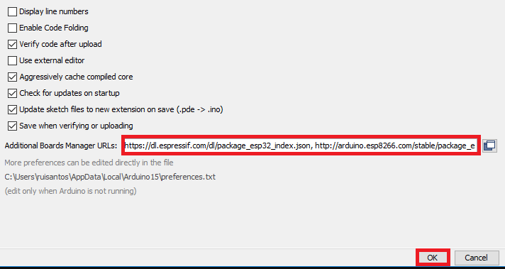
Note: If you already have installed other board manager like ESP8266 then enter the comma to seperate the different board URL. Like this:
https://dl.espressif.com/dl/package_esp32_index.json, http://arduino.esp8266.com/stable/package_esp8266com_index.json
3. Open the Boards Manager. Go to Tools > Board > Boards Manager…
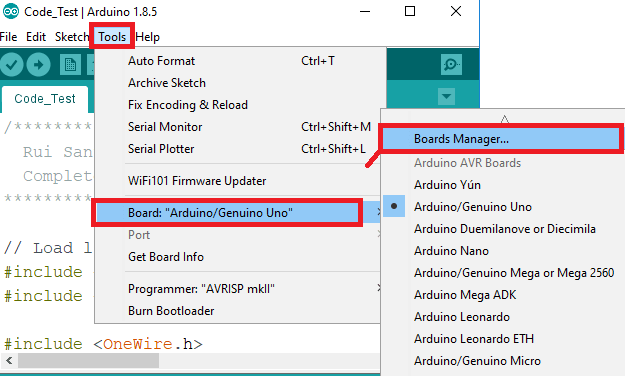
4. Search for ESP32 and press the install button for the “ESP32 by Espressif Systems“:

5. That’s it. It should be installed after a few seconds.
Source Code & Getting Started with ESP32 CAM
Now, go to the files menu and then select examples. From the examples menu, select the ESP32 >> Camera >> CameraWebServer Sketch.
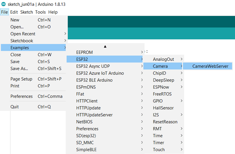
So this is the basic example code of ESP32 CAM WebServer for Video Streaming. The code is very complicated due to so many files.
You just need to modify the code by uncommenting the ESP32 CAM model that you are using. If you are using ESP32 CAM from AI-Thinker uncomment the AI-Thinker Part and comment rest of the part.
//#define CAMERA_MODEL_WROVER_KIT // Has PSRAM
//#define CAMERA_MODEL_ESP_EYE // Has PSRAM
//#define CAMERA_MODEL_M5STACK_PSRAM // Has PSRAM
//#define CAMERA_MODEL_M5STACK_V2_PSRAM // M5Camera version B Has PSRAM
//#define CAMERA_MODEL_M5STACK_WIDE // Has PSRAM
//#define CAMERA_MODEL_M5STACK_ESP32CAM // No PSRAM
#define CAMERA_MODEL_AI_THINKER // Has PSRAM
//#define CAMERA_MODEL_TTGO_T_JOURNAL // No PSRAM
You also need to change your Wi-Fi Network credentials like SSID and Password.
const char* ssid = "*********";
const char* password = "*********";
Now, let’s start to program ESP32 CAM. Open your Arduino IDE. Go to tools >> select the ESP32 Board >> from the list select AI-Thinker ESP32-CAM.
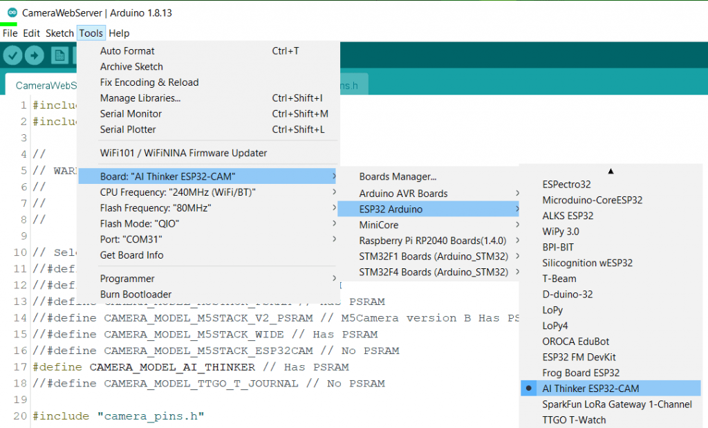
Now connect the FTDI Module to your Computer and select the COM Port. Finally, you can upload the code. The code will take more than a minute to compile and upload.
Recommended Readings:
- ESP32 based MAX30100 Pulse Oximeter Webserver
- Portable ESP32 WiFi Repeater
- ESP32 based Patient Health Monitoring System
ESP32 CAM Video Streaming Over WiFi
Once the code is uploaded successfully, you can open the Serial Monitor. Meanwhile, if you press the reset button on the Serial Monitor you will see the device is in downloading mode.

In order to disable the downloading mode. Simply remove the IO0 GND Jumper from the Module. Now again press the reset button. So the device will connect to the Wi-Fi Network. Once the device gets connected, it will display its local IP Address.
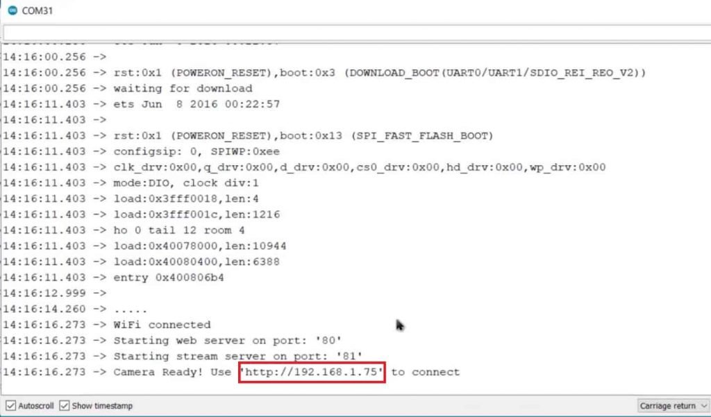
You can Copy this IP Address Link and paste it on your favorite web browsers. A simple web interface will appear. you will find all the camera settings on the left side. Simply explore each settings manually to know more about it.
At the bottom of the web page you can see there is an option to stream, you can click on stream option to see the video. Not only that you can also Maximize the resolution using the Camera Option.
You can move the camera module to see yourself in the video. The Video data is live and you are observing it on the local Web server.
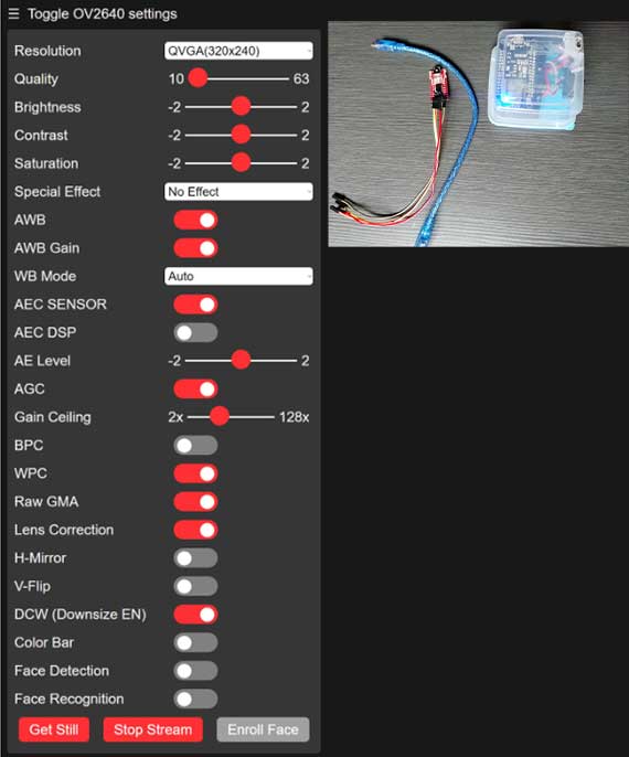
There is an option “Get Still” to capture the image as well. It will store the capture image on SD Card.
Printed 3D Enclosure for ESP32-CAM
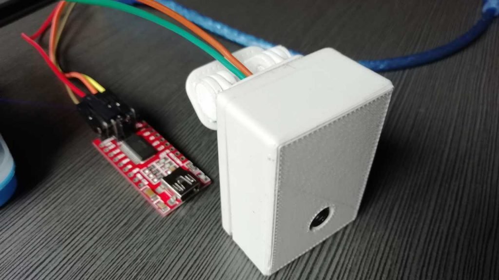
Here, I have designed a ESP32-CAM enclosure and holder so that we can place it anywhere and use as a surveillance camera.
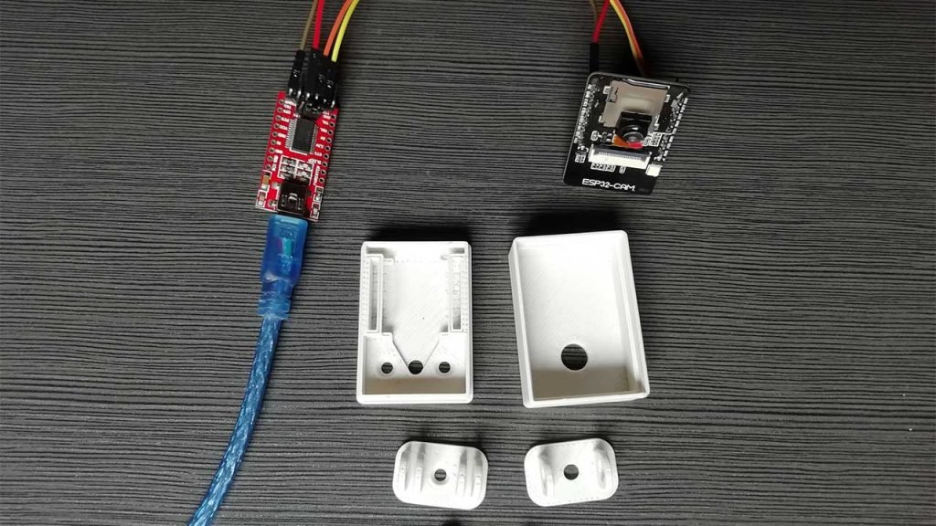
The 3D files are provided below simply download it. If you don’t have 3D printer then PCBWay will help you. Recently PCBWay started CNC 3D Printing services. So,there is a $25 SALE on custom metal & plastic parts. Grab this Custom Prototype Manufacturing Service now.
After assembling all the parts our ESP32 CAM is ready for video streaming over Wi-Fi.
Video Tutorial & Guide
Wrapping up
So this is how you Program ESP32 CAM to Stream Video Over Wi-Fi. The advantage of this project is you can use the ESP32 CAM as a surveillance camera. You can place it outside your house and use it as a Security Device.

