In this guide, you will learn about the ESP8266 Manual Wifi Configuration with EEPROM without Hard-Code network certificates. You can learn how to configure WiFi settings on the ESP8266 board, without hard coding and by saving again. Here we will use an EEPROM library that allows you to connect your ESP8266 to various Access Points (APs) without hard-coding and upload new code to your board. ESP8266 WiFi-Manager library is a way to manually configure the wifi but, we will not use it here.
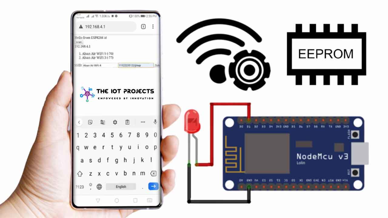
All IoT products in 2020 only work like this. Initially, they all act as hotspots. Then you need to connect your phone or PC to that hotspot. Once the hotspot is connected, then go to the special IP address (192.168.4.1) and then enter the WiFi certificates, and then it is automatically connected to the home router or WiFi. So most IoT devices are built using ESP8266 which helps you set up network configuration (for example SSID, and WiFi router password) through a form and stored in its memory.
ESP8266 Manual Wifi Configuration with EEPROM
Here we will build an IoT device, using the ESP8266 Manual Wifi Configuration with EEPROM. that will help you set up the network configuration (for example SSID, and the password of the WiFi router) via a form and store it in its EEPROM memory. It’s a little harder to do then the Arduino boards. The ESP8266 doesn’t really have EEPROM like all real Arduino boards do. That’s why most of us struggle to use the EEPROM library with the ESPP66 development board.
You do not have to hard-code your network credentials (SSID and password) using this feature. Your ESP will automatically join known networks or set up access points that you can use to configure network credentials.
How do ESP8266 Manual WiFi Configuration Works?
- When your ESP8266 boots, it sets up in station mode and tries to connect to a previously saved access point (a known SSID and password combination).
- If this process fails, it sets ESP to access point mode.
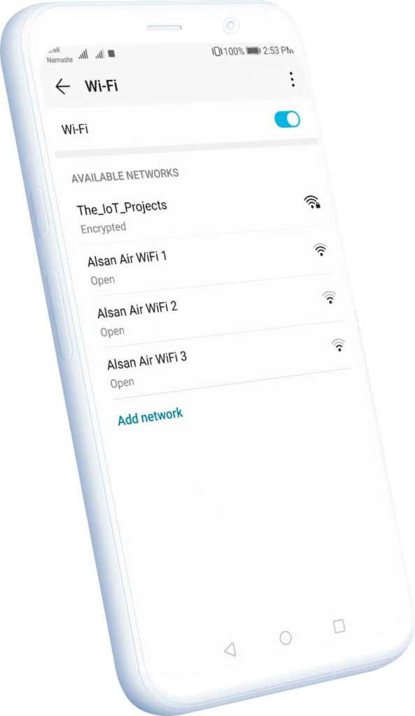
- Using any WiFi-enabled device with any browser, connect to the newly created AP.
- After establishing a connection with the newly created access point. You can go to the default IP address 192.168.4.1 to open a web page that allows you to configure your SSID and password.
- Once the new SSID and password are set the ESP reboots and tries to connect.
- If it establishes a connection, the process ends successfully. Otherwise, it will be established as an Access Point again.
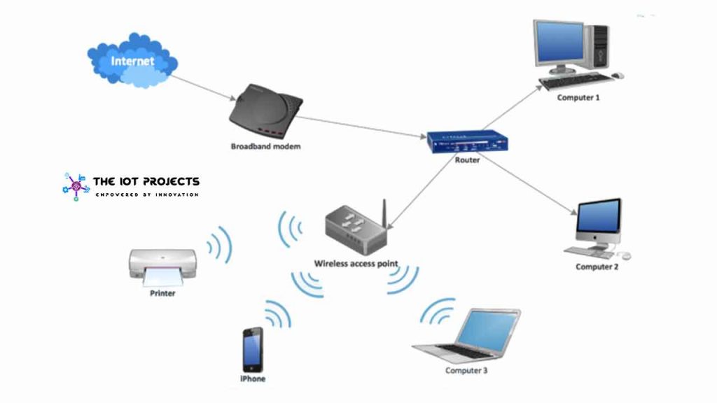
What is Access Point?
An access point is a device that creates a wireless local area network. Or WLAN, usually in an office or large building. An access point is sometimes connected to a wired router, switch, or hub via an Ethernet cable, and a Wi-Fi signal project in a specified area. It is used to configure IoT devices for first time users or password changes.
Program Code Explanation
In this ESP8266 Manual WiFi configuration project, ESP8266 with EEPROM has 3 sections for manual WiFi configuration work. The first one (EEPROM Conundrum), where we will see how to write data in ESP8266 memory.
ESP8266 can be problematic to write values other than integers to memory. The main reason is that the standard EEPROM library does not work because ESP8266 does not have EEPROM. The library we use only emulates EEPROM but in real life, we are writing in flash memory.
#include <ESP8266WiFi.h>
#include <ESP8266HTTPClient.h>
#include <ESP8266WebServer.h>
#include <EEPROM.h>

//Variables
int i = 0;
int statusCode;
const char* ssid = "text";
const char* passphrase = "text";
String st;
String content;


//Function Decalration
bool testWifi(void);
void launchWeb(void);
void setupAP(void);

//Establishing Local server at port 80 whenever required
ESP8266WebServer server(80);
Everything we write in ESP8266 memory must be striped, and we can write them one letter at a time. First, we declare the string variable st and content and some complete geek and const four *.
We will then announce the following three different actions:
bool testWifi(void);
void launchWeb(void);
void setupAP(void);
Serial.begin(115200); //Initialising if(DEBUG)Serial Monitor
Serial.println();
Serial.println("Disconnecting previously connected WiFi");
WiFi.disconnect();
EEPROM.begin(512); //Initialasing EEPROM
delay(10);
pinMode(LED_BUILTIN, OUTPUT);
Serial.println();
Serial.println();
Serial.println("Startup");In ESP8266 Manual Wifi Configuration with EEPROM without Hard-Code. First, start the EEPROM function with EEPROM.begin. And then also set the storage size. Next cycle through string value.
String esid;
for (int i = 0; i < 32; ++i)
{
esid += char(EEPROM.read(i));
}
Serial.println();
Serial.print("SSID: ");
Serial.println(esid);
Serial.println("Reading EEPROM pass");
String epass = "";
for (int i = 32; i < 96; ++i)
{
epass += char(EEPROM.read(i));
}
Serial.print("PASS: ");
Serial.println(epass);
WiFi.begin(esid.c_str(), epass.c_str());
if (testWifi())
{
Serial.println("Succesfully Connected!!!");
return;
}
else
{
Serial.println("Turning the HotSpot On");
launchWeb();
setupAP();// Setup HotSpot
}
Serial.println();
Serial.println("Waiting.");
while ((WiFi.status() != WL_CONNECTED))
{
Serial.print(".");
delay(100);
server.handleClient();
}Initially, ESP8266 is set up in station mode and tries to connect to previously saved access points from EEPROM memory. If a correct access point network is found, it will be connected to it.
If this process fails, it sets ESP8266 to access point mode and creates a hotspot network.
void loop() {
if ((WiFi.status() == WL_CONNECTED))
{
for (int i = 0; i < 10; i++)
{
digitalWrite(LED_BUILTIN, HIGH);
delay(1000);
digitalWrite(LED_BUILTIN, LOW);
delay(1000);
}
}
else
{
}In this section, you can enter your code as you wish. For now, I just blink the LED.
void createWebServer()
{
{
server.on("/", []() {
IPAddress ip = WiFi.softAPIP();
String ipStr = String(ip[0]) + '.' + String(ip[1]) + '.' + String(ip[2]) + '.' + String(ip[3]);
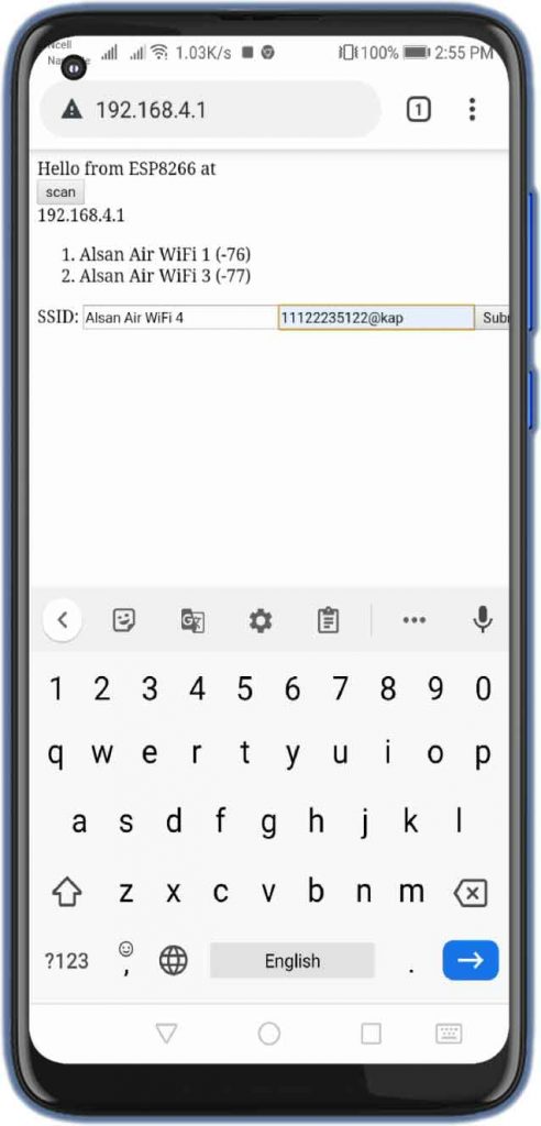
content = "<!DOCTYPE HTML>rn<html>Hello from ESP8266 at ";
content += "<form action="/scan" method="POST"><input type="submit" value="scan"></form>";
content += ipStr;
content += "<p>";
content += st;
content += "</p><form method='get' action='setting'><label>SSID: </label><input name='ssid' length=32><input name='pass' length=64><input type='submit'></form>";
content += "</html>";
server.send(200, "text/html", content);
});
server.on("/scan", []() {
//setupAP();
IPAddress ip = WiFi.softAPIP();
String ipStr = String(ip[0]) + '.' + String(ip[1]) + '.' + String(ip[2]) + '.' + String(ip[3]);
content = "<!DOCTYPE HTML>rn<html>go back";
server.send(200, "text/html", content);
});Project Demonstration
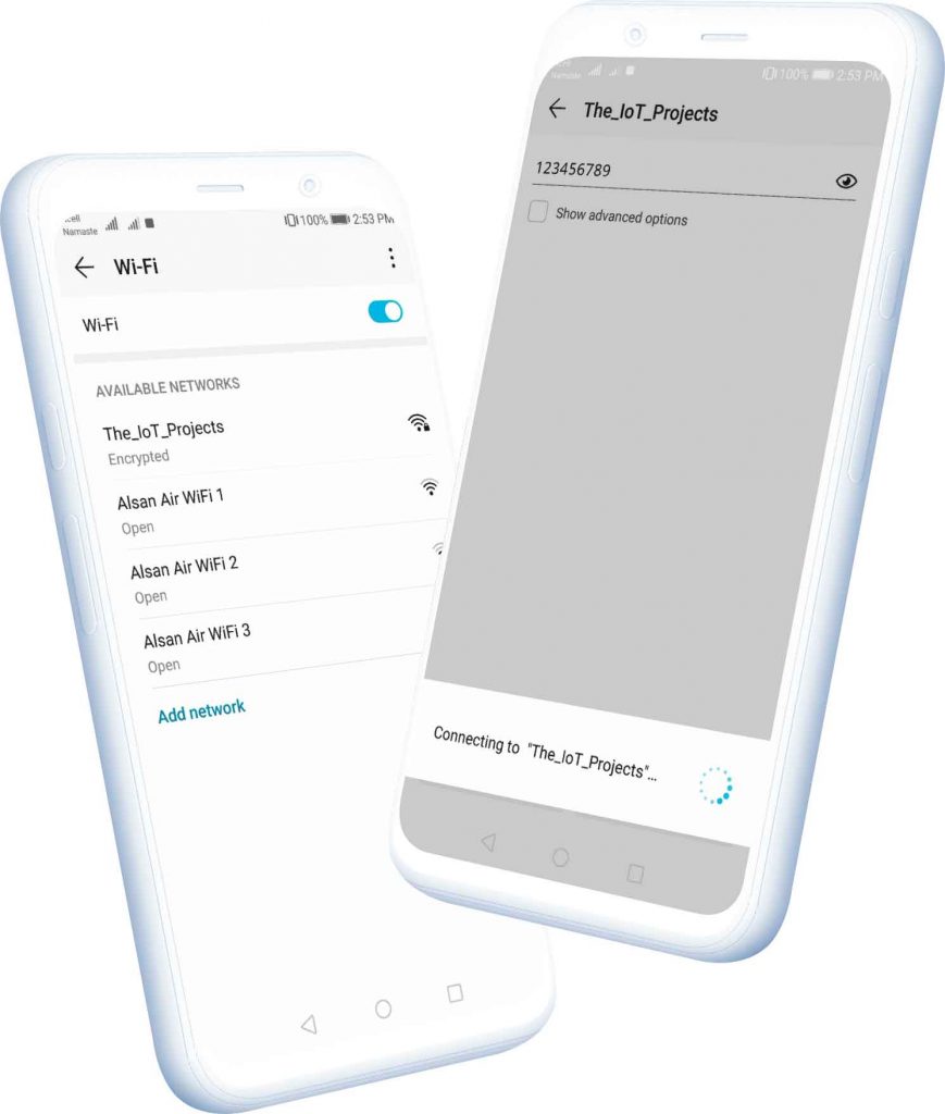
Using any WiFi-enabled device with any browser, connect to the newly created AP. After establishing a connection with the newly created access point, you can go to the default IP address 192.168.4.1 to open a web page that allows you to configure your SSID and password.
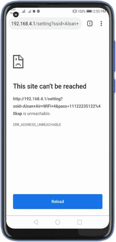
Once the new SSID and password are set, ESP reboots and tries to connect. If it establishes a connection, the process ends successfully. Otherwise, it will again be established as an access point.
Source Code/Program
This is a complete source code for ESP8266 Manual Wifi Configuration with EEPROM without Hard-Code projects. Copy the below code in Arduino IDE and upload it to your ESP board by selecting the correct port.
#include <ESP8266WiFi.h>
#include <ESP8266HTTPClient.h>
#include <ESP8266WebServer.h>
#include <EEPROM.h>
//Variables
int i = 0;
int statusCode;
const char* ssid = "text";
const char* passphrase = "text";
String st;
String content;
//Function Decalration
bool testWifi(void);
void launchWeb(void);
void setupAP(void);
//Establishing Local server at port 80 whenever required
ESP8266WebServer server(80);
void setup()
{
Serial.begin(115200); //Initialising if(DEBUG)Serial Monitor
  Serial.println();
  Serial.println("Disconnecting previously connected WiFi");
  WiFi.disconnect();
  EEPROM.begin(512); //Initialasing EEPROM
  delay(10);
  pinMode(LED_BUILTIN, OUTPUT);
  Serial.println();
  Serial.println();
  Serial.println("Startup");
//---------------------------------------- Read EEPROM for SSID and pass
Serial.println("Reading EEPROM ssid");
String esid;
  for (int i = 0; i < 32; ++i)
  {
    esid += char(EEPROM.read(i));
  }
  Serial.println();
  Serial.print("SSID: ");
  Serial.println(esid);
  Serial.println("Reading EEPROM pass");

  String epass = "";
  for (int i = 32; i < 96; ++i)
  {
    epass += char(EEPROM.read(i));
  }
  Serial.print("PASS: ");
  Serial.println(epass);


  WiFi.begin(esid.c_str(), epass.c_str());
  if (testWifi())
  {
    Serial.println("Succesfully Connected!!!");
    return;
  }
  else
  {
    Serial.println("Turning the HotSpot On");
    launchWeb();
    setupAP();// Setup HotSpot
  }

  Serial.println();
  Serial.println("Waiting.");

  while ((WiFi.status() != WL_CONNECTED))
  {
    Serial.print(".");
    delay(100);
    server.handleClient();
  }
}
void loop() {
  if ((WiFi.status() == WL_CONNECTED))
  {

    for (int i = 0; i < 10; i++)
    {
      digitalWrite(LED_BUILTIN, HIGH);
      delay(1000);
      digitalWrite(LED_BUILTIN, LOW);
      delay(1000);
    }

  }
  else
  {
  }
}
//-------- Fuctions used for WiFi credentials saving and connecting to it which you do not need to change
bool testWifi(void)
{
int c = 0;
Serial.println("Waiting for Wifi to connect");
while ( c < 20 ) {
if (WiFi.status() == WL_CONNECTED)
{
return true;
}
delay(500);
Serial.print("*");
c++;
}
Serial.println("");
Serial.println("Connect timed out, opening AP");
return false;
}
void launchWeb()
{
Serial.println("");
if (WiFi.status() == WL_CONNECTED)
Serial.println("WiFi connected");
Serial.print("Local IP: ");
Serial.println(WiFi.localIP());
Serial.print("SoftAP IP: ");
Serial.println(WiFi.softAPIP());
createWebServer();
// Start the server
server.begin();
Serial.println("Server started");
}
void setupAP(void)
{
WiFi.mode(WIFI_STA);
WiFi.disconnect();
delay(100);
int n = WiFi.scanNetworks();
Serial.println("scan done");
if (n == 0)
Serial.println("no networks found");
else
{
Serial.print(n);
Serial.println(" networks found");
for (int i = 0; i < n; ++i)
{
// Print SSID and RSSI for each network found
Serial.print(i + 1);
Serial.print(": ");
Serial.print(WiFi.SSID(i));
Serial.print(" (");
Serial.print(WiFi.RSSI(i));
Serial.print(")");
Serial.println((WiFi.encryptionType(i) == ENC_TYPE_NONE) ? " " : "*");
delay(10);
}
}
Serial.println("");
st = "<ol>";
for (int i = 0; i < n; ++i)
{
// Print SSID and RSSI for each network found
st += "<li>";
st += WiFi.SSID(i);
st += " (";
st += WiFi.RSSI(i);
st += ")";
st += (WiFi.encryptionType(i) == ENC_TYPE_NONE) ? " " : "*";
st += "</li>";
}
st += "</ol>";
delay(100);
WiFi.softAP("The_IoT_Projects", "123456789");
Serial.println("softap");
launchWeb();
Serial.println("over");
}
void createWebServer()
{
 {
    server.on("/", []() {

      IPAddress ip = WiFi.softAPIP();
      String ipStr = String(ip[0]) + '.' + String(ip[1]) + '.' + String(ip[2]) + '.' + String(ip[3]);
      content = "<!DOCTYPE HTML>rn<html>Hello from ESP8266 at ";
      content += "<form action="/scan" method="POST"><input type="submit" value="scan"></form>";
      content += ipStr;
      content += "<p>";
      content += st;
      content += "</p><form method='get' action='setting'><label>SSID: </label><input name='ssid' length=32><input name='pass' length=64><input type='submit'></form>";
      content += "</html>";
      server.send(200, "text/html", content);
    });
    server.on("/scan", []() {
      //setupAP();
      IPAddress ip = WiFi.softAPIP();
      String ipStr = String(ip[0]) + '.' + String(ip[1]) + '.' + String(ip[2]) + '.' + String(ip[3]);

      content = "<!DOCTYPE HTML>rn<html>go back";
      server.send(200, "text/html", content);
    });
server.on("/setting", []() {
String qsid = server.arg("ssid");
String qpass = server.arg("pass");
if (qsid.length() > 0 && qpass.length() > 0) {
Serial.println("clearing eeprom");
for (int i = 0; i < 96; ++i) {
EEPROM.write(i, 0);
}
Serial.println(qsid);
Serial.println("");
Serial.println(qpass);
Serial.println("");
Serial.println("writing eeprom ssid:");
for (int i = 0; i < qsid.length(); ++i)
{
EEPROM.write(i, qsid[i]);
Serial.print("Wrote: ");
Serial.println(qsid[i]);
}
Serial.println("writing eeprom pass:");
for (int i = 0; i < qpass.length(); ++i)
{
EEPROM.write(32 + i, qpass[i]);
Serial.print("Wrote: ");
Serial.println(qpass[i]);
}
EEPROM.commit();
content = "{"Success":"saved to eeprom... reset to boot into new wifi"}";
statusCode = 200;
ESP.reset();
} else {
content = "{"Error":"404 not found"}";
statusCode = 404;
Serial.println("Sending 404");
}
server.sendHeader("Access-Control-Allow-Origin", "*");
server.send(statusCode, "application/json", content);
});
}
}Video Demonstration: ESP8266 Manual Wifi Configuration with EEPROM
This is a complete video demonstration on ESP8266 Manual Wifi Configuration with EEPROM without Hard coding it.

Conclusion
In this tutorial, I have shown you ESP8266 Manual Wifi Configuration with EEPROM without Hard-Code. This tutorial will be helpful to built ESP8266 based IoT device. I hope you enjoyed reading this article. If you have any questions, comments, or ideas? Let me know in the comment section below.
These are some ESP8266 based IoT Projects:
- Secure HTTPS Requests to URL Using NodeMCU ESP8266
- IoT Based Patient Health Monitoring System Using ESP8266/ESP32 Web Server
- BME280 Based Mini Weather Station using ESP8266/ESP32
- ESP8266 based IoT Health Care Panic Alarm for Elderly Folks
- Home Automation with ESP8266 Web Server & Relay Module Control Appliances from Local Network
- Home Automation with MIT App Inventor and ESP8266
- RFID Based Attendance System Using NodeMCU with PHP Web App
- ESP8266 RGB LED Controller Web Server
- Password Security Lock System Using Arduino & Keypad
- Temperature Controlled Home Automation using Arduino
- ESP8266 Plot Sensor readings to Webserver in Real-Time Chart


Great work!! I have it running and would like to add html. I can see my ip address that my dhcp server gave it and then would like to go to that IP and see html but don’t know were to put my html. I can take the LED blink out of the loop but don’t think my code would go in a loop. I added server.on(“/”, handleRootPath); at the bottom of the void setup then added another function called the same with server.send(200, “text/html”, index_html); in it. I use const char index_html[] PROGMEM {} with my html inside the brackets. So far I can’t get a html page to show up at the ip address it was given. What do I do??
Thanks again
Add your custom code in loop section. Just replace that LED Blink code with your own code. Thats all !!!
Sorry I put this code in the loop section.. server.send(200, “text/html”, index_html); and it just kept trying to connect and never could. I commented it out and it connected so that can’t be the answer. If the code is in a loop it just keeps going on forever, there has to be another way.
I was able to get my code to work but not in the void loop. I had to add in that loop the server.handleClient(); and then put the rest of my code in your if (testWifi()) statement. Anyone else can now add more code there. If its going to go forever in a loop then add code there as well. Let me know if I am wrong but I could get anything to work in that loop that need to only run 1 time.
I have another idea but not that good yet at coding, but could it instead of using the 96 bytes(not sure if they are called bytes) in your code for the eeprom use a way to put a character after the ssid like a | or ; so that if the ssid and password are only say 20 use what’s needed thus saving the flash memory. In other coding I would split or parse on that character every time it sees it. I am pretty sure it can be done but I am not that familiar yet with this codding. Then if you need to use more of the memory you can keep adding more but may have to do some kind of count so it doesn’t go over the memory you have.
Nice, Alsan Parajuli.
In many projects I used the WifiManager before but I am not so happy with the way what to do when I want to change the WiFi connection. The way you presents it here looks pretty easy to use but I was wondering if it is possible to change the form to scan and set the SSID/password (now in the sketch) to a html file on spiff? Any pointers?
Yes it is possible. You can find lots of tutorial on YouTube as well. If you have some knowledge of HTML and CSS you can also redesign it for best user experience.
thank you
Hello
that was perfect
Is it possible to change the project code so that when we enter the ssid and password in the web server, it enters a page to control the gpio bases?
Is this possible? Do you have training?
Yes Possible
Token info: type = id token (GITKit token), status = on request
Token info: type = id token (GITKit token), status = error
Token error: code: -4, message: connection lost
stream begin error, connection lost
Olá gostei muito do seu projeto tem como ele mostrar o novo IP na web obrigado