Interfacing DHT11 Humidity and Temperature Sensor with Arduino & LCD
Overview
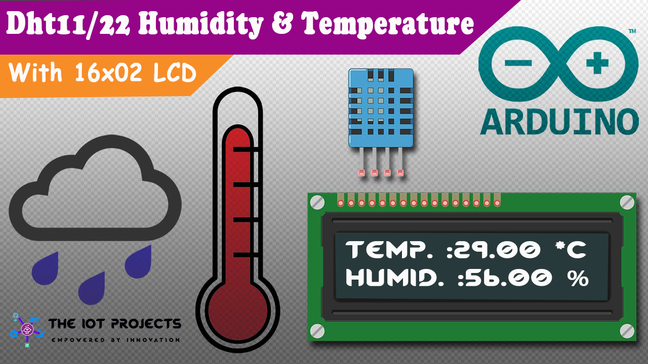
Welcome to The IoT Projects. In this tutorial, we are going in-depth with a DHT11 sensor that measures Humidity and Temperature. We will also interface LCD Screen and DHT11 Temperature and Humidity Sensor to the Arduino by Programming it. Hence today’s topic is all about Interfacing DHT11 Humidity and Temperature Sensor with Arduino & LCD.
Basically, the DHT11 Humidity and Temperature Sensor is Pre Calibrated, i.e. we don’t need any extra components to start measuring relative Humidity and Temperature. Actually, DHT11 is a calibrated digital Sensor that has high reliability and longterm excellent stability. The sensor includes a resistive element like NTC. NTC is a temperature measuring sensor. Hence, DHT11 has good quality and durability. The best thing that we love about this sensor is inexpensive.
Components Required
- Arduino UNO
- DHT11/DHT22 Humidity and Temperature Sensor
- 10K Potentiometer
- 16×02 LCD Screen
- Breadboard
- Jumper Wires: Male to Male and Male to Female
Hardware Overview of DHT11 Sensor
DHT11 is a Digital Humidity and Temperature Sensor. It measures humidity from 20 to 80% with an accuracy of 5%. Similarly, the temperature from 0°C to 50°C with ±2.0°C accuracy.
Usually, DHT11 requires a 10k-ohm external pull-up resistor between VCC and Digital Pin for proper interfacing. However, the DHT11 module has built-in resistors. Hence, an additional resistor is not required. It also has a decoupling capacitor to filter noise on the power supply.
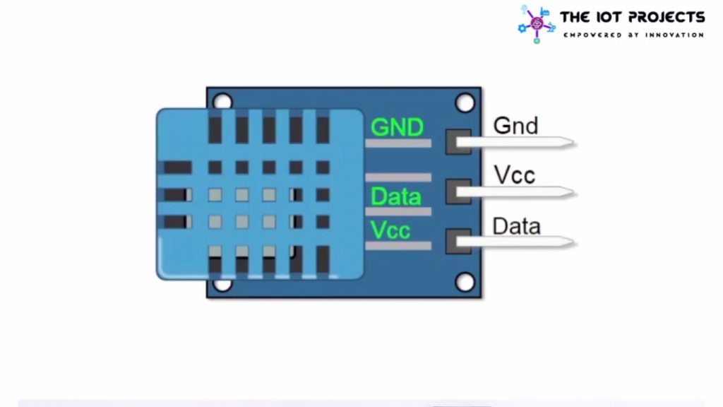
This sensor provides data to the Arduino using Data Pin. The power supply pin(VCC) can be connected to the range of 3.5 to 5 volts.
Working Principle
The sensor includes a humidity sensing component, an NTC temperature sensor (or thermistor) and an IC on the rear side of the sensor.
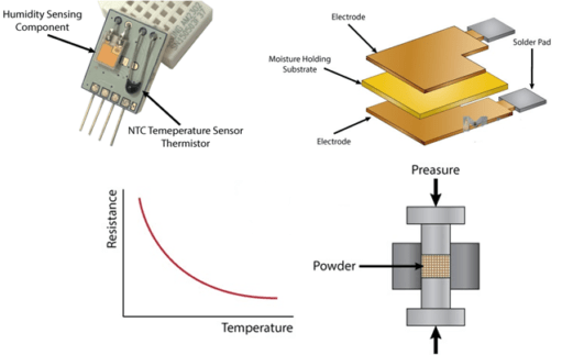
Basically, for measuring temperature these sensors use an NTC temperature sensor or a thermistor. A thermistor is truly a variable resistor that changes its resistance with the change of the temperature. These sensors are made by sintering of semiconductive materials like ceramics or polymers in order to produce larger changes within the resistance with just small changes in temperature. The term “NTC” means “Negative Temperature Coefficient”, which suggests that the resistance decreases with an increase in the temperature.
Features of DHT11 Sensor
- Cheap in Price.
- 3 to 5V power and I/O
- 2.5mA max current use during conversion (while requesting data)
- Good for 20-80% humidity readings with 5% accuracy
- Good for 0-50°C temperature readings ±2°C accuracy
- No over 1 Hz rate (once every second)
- Body size 15.5mm x 12mm x 5.5mm
- 3 pins with 0.1″ spacing
Interfacing DHT11 Humidity & Temperature Sensor with Arduino & LCD
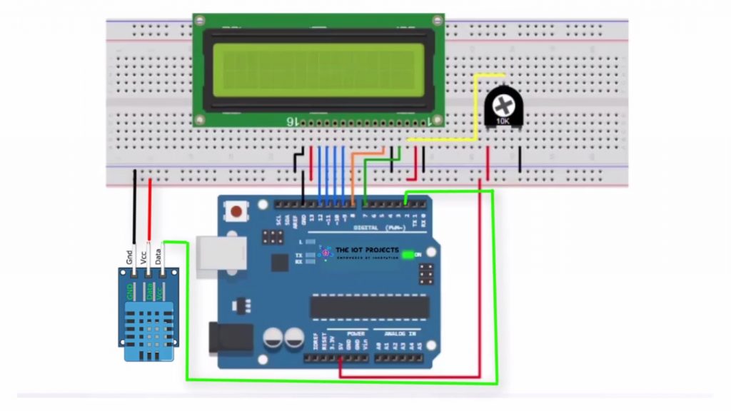
Now lets wire up DHT11 and LCD to the Arduino board. The Connection is fairly simple. First of all, interface the LCD to the Arduino.
LCD to Arduino Connection
- RS pin to digital pin 7
- Enable pin to digital pin 8
- D4 pin to digital pin 9
- D5 pin to digital pin 10
- D6 pin to digital pin 11
- D7 pin to digital pin 12
- R/W pin to ground
- VSS pin to ground
- VCC pin to 5V
Connection with 10K Potentiometer:
- VO pins to Center Pin of the Potentiometer.
- Ends to +5V and Ground
Interfacing DHT11
- Connect the Ground(GND) of the Arduino board to the GND pin of the Arduino
- Now, connect 5 volts to the VCC pin.
- Finally, connect the pin number 2 of the Arduino board to the Data Pin of the DHT-11 Sensor.
Program Sketch/Codes: Explanation
Now, let’s program the Arduino board using this sketch. But, before that let me explain these few lines of codes. So that it will be easier to understand the codes.
These lines of code include LiquidCrystal and DHTLib library files.
#include <LiquidCrystal.h>
#include <dht.h>
The OutPin defines the Data pin connected to the Arduino.
#define outPin 2Basically, these two lines define the LCD Data Pins and Create LCD and DHT objects.
LiquidCrystal lcd(7, 8, 9, 10, 11, 12); // Create an LCD object.
dht DHT;    // Create a DHT object
LCD.begin command to Initialize the LCD.
lcd.begin(16,2); // Initialize the LCDIn the Loop function, we have used the read11 function. It reads data from the sensor.
void loop() {
  int readData = DHT.read11(outPin);
Float is used to read temperature and Humidity when they are calculated.
float t = DHT.temperature;
  float h = DHT.humidity;
Char function is used to display small degree characters to the LCD Screen and “%” Symbol for Humidity.
lcd.setCursor(0,0);
  lcd.print("Temp.: ");
  lcd.print(t);
  lcd.print((char)223);//shows degrees character
  lcd.print("C");

  lcd.setCursor(0,1);
  lcd.print("Humi.: ");
  lcd.print(h);
  lcd.print("%");
Under the loop function, we added a 1-sec delay. Therefore, we sent the data every second.
delay(1000);Final Program Sketch/Codes
This is the final sketch of this project. Using this sketch you can interface DHT11 Sensor with Arduino and Display the final output to the LCD Screen.
//https://iotprojectsideas.com

#include <LiquidCrystal.h>  // Include LiquidCrystal Library
#include <dht.h>   // Include DHTlib Library- Download from Description.

#define outPin 2

LiquidCrystal lcd(7, 8, 9, 10, 11, 12); // Create an LCD object.
dht DHT;    // Create a DHT object

void setup() {
  lcd.begin(16,2); // Initialize the LCD
}

void loop() {
  int readData = DHT.read11(outPin);

  float t = DHT.temperature;
  float h = DHT.humidity;

  lcd.setCursor(0,0);
  lcd.print("Temp.: ");
  lcd.print(t);
  lcd.print((char)223);//shows degrees character
  lcd.print("C");

  lcd.setCursor(0,1);
  lcd.print("Humi.: ");
  lcd.print(h);
  lcd.print("%");

  delay(1000);
}
Video Tutorials:
Conclusion:
Finally, we have completed Interfacing DHT11 Humidity and Temperature Sensor with Arduino & LCD. Now, you can see the Humidity and Temperature from the LCD Screen. We hope you found this project useful! Drop a comment below if you have any doubts or queries. We’ll do our best to answer your questions.

Can this DHT 11 be used to measure the temperature of a human being apart from the room temperature and humidity???
No it won’t provide you accurate value