Introduction
Every electronics enthusiast and Hobbyist loves Arduino’s right! we all use board like Arduino UNO, Nano, Pro Mini, or any other similar Arduino even for some basic projects. For tiny projects like displaying a straightforward message on LCD or simply Fading LED would be a waste of resources and money. In this tutorial, I discovered an inexpensive and Compact Alternative to Arduino called ATTINY85. So, today you will learn to Program Digispark Attiny85 with Arduino IDE.
Components Required
| S.N | Components Name | Description | Quantity | |
|---|---|---|---|---|
| 1 | DigiSpark Attiny85 Board | DigiSpark Attiny85 Arduino Compatible Board | 1 | https://amzn.to/32km6UD |
| 2 | Arduino IDE | Arduino Programming Software | 1 | https://www.arduino.cc/en/software |
About Attiny85 Board
Attiny85 is like Arduino, but it is not Arduino, ATTINY85 is a Micro-Controller chip, which has 6 General Purpose I/O pins (GPIO), out of which 5 are PWM enabled, and ATTINY85 also supports the SPI and I2C Communication Protocols, but it’s only 8Kb of programming memory, so yes, it’s not as capable as Arduino board, but it’ll work just fine for tiny projects.
It also has some more features like:
- Inbuilt 8-Bit timers.
- Inbuilt comparators.
- 512 Bytes of EPROM
- 512 Bytes of SRAM.
Here, is a complete datasheet for a brief knowledge.
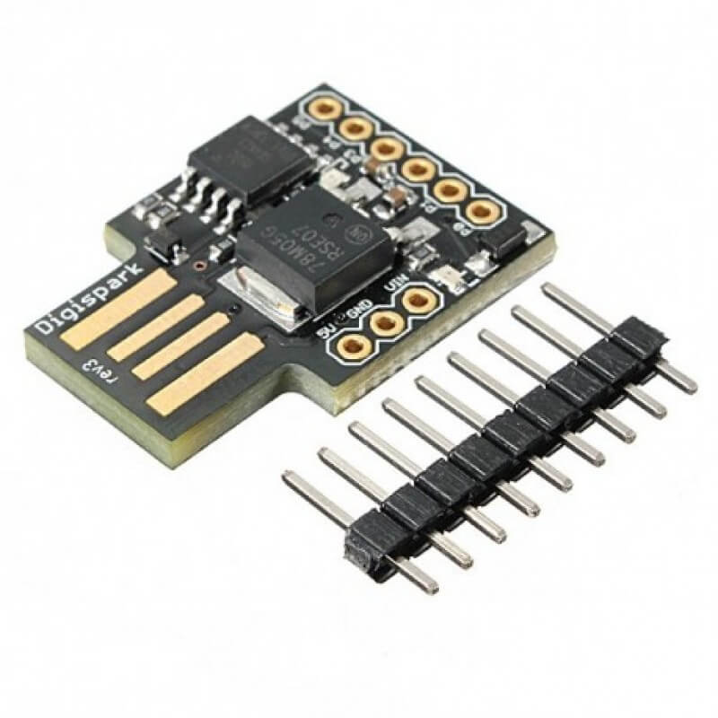
This Attiny85 comes in a module and standalone chip. I would never recommend you guys to use this chip and rather go for a module that comprises a voltage regulator and can be directly plugged into your computer. But before you plug it into the computer, some things needed to be set up.
About the sponsor: This article is sponsored by PCBway Company, one of the most experienced PCB and PCB assembly manufacturers. They produce high-quality PCBs at a reasonable price, only $5 for 10 PCBs and a total of $30 for 20 PCB assembly. In addition, new members also receive a $5 bonus.
Setup Arduino IDE for Digispark Attiny85
We need to add (DigiStump’s Attiny85) boards into our Arduino IDE.
Add DigiStump Board URL
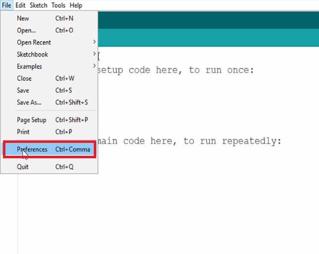
First, open your Arduino IDE, Go to Preference and simply paste the link “ https://raw.githubusercontent.com/digistump/arduino-boards-index/master/package_digistump_index.json,” on the additional Board Management URL.
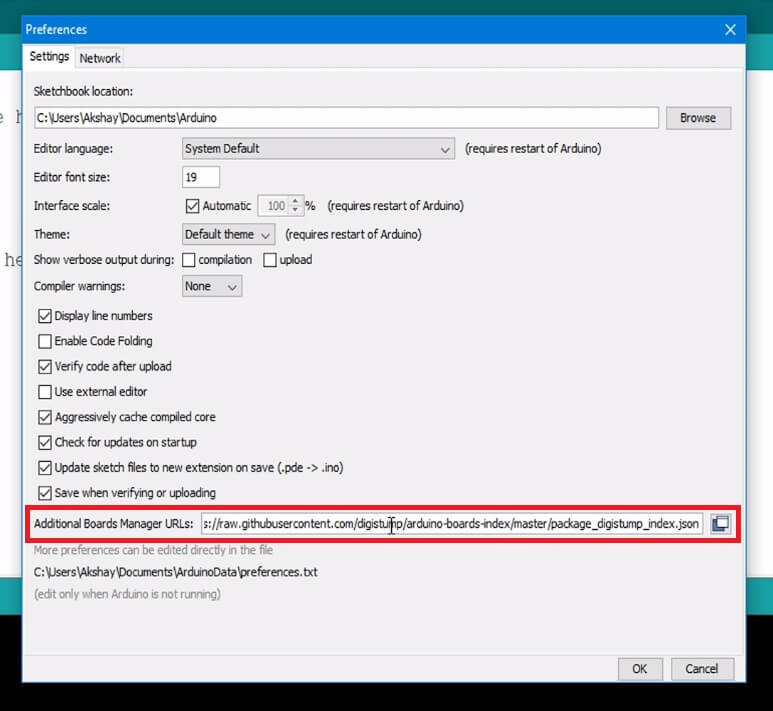
Then simply Press okay and Close Preferences.
Install DIGISTUMP AVR Board Manager
To install Attiny85 Board Settings on Arduino IDE go to board manager, under the Tools menu select the Contributed type of boards Option.
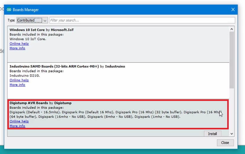
Select “DIGISTUMP AVR BOARDS“
Click on install to install it!
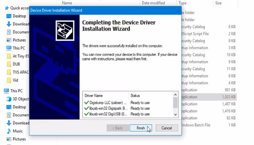
Install Attiny85 Device Driver
Now, install the drivers on your computer Attached on this Step
Unzip the Attached File. Click on DPinst64.exe to install the Drivers on your computer.
Now, insert the Attiny85 board into your computer. Sometimes your drivers aren’t installed correctly, in such an (unusual) case, we are going to follow these steps
Open Device Manager. Click on the View menu and select “Show Hidden option” Click on Device called “Libusb-win”
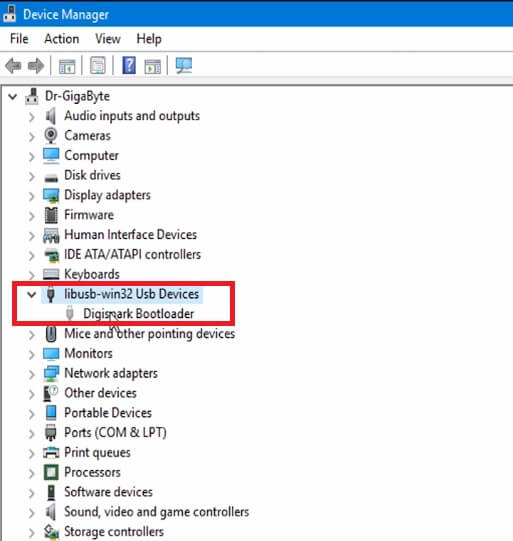
Right Click on the DigiSpark USB device and Click on Update Device. Browse the drivers from our computer. Finally, select the location of drivers stored on a computer
- Getting Started with Arduino UNO
- IoT Weather Station using DHT11 Sensor
- Top 10 IoT (Internet of Things) Projects
- IoT Web Controlled Smart Notice Board using NodeMCU ESP8266
Attiny85 Blink Test Program Code
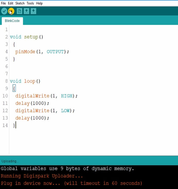
Now, let’s run a test code to examine our ‘Attiny85’ board. We will simply try Blink code, which you can copy from below
void setup()
{
pinMode(1, OUTPUT);
}
void loop()
{
digitalWrite(1, HIGH);
delay(1000);
digitalWrite(1, LOW);
delay(1000);
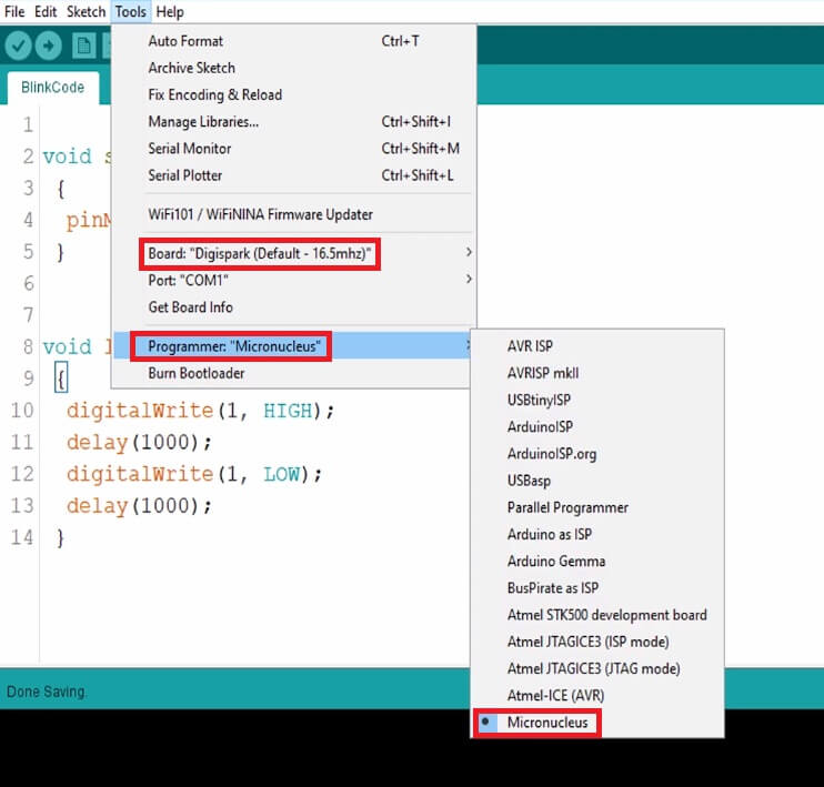
}Select Proper Board Type
Here, Selecting the correct Code is that the deal-breaker of this complete Setup. to do so, we will Select “Digispark (Default-16.5Mhz)” from Board Menu in Tools. Then finally, select programmer as “Micronucleus” from Board Menu in Tools.
Uploading the Code
Usually, we’d compile and Upload the code with our Arduino Connected. But here in Attiny85, we will Compile the code and press the UPLOAD button. Waits for the Plug-in device now… (will timeout in 60 seconds) message.
Connect the Board Within 60 Seconds.
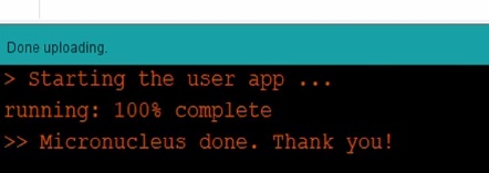
Wait for “Micronucleus done. Thank you!” Message From compiler.
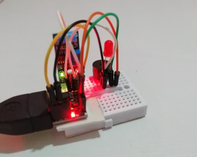
Enjoy! The output of this code will show blinking LED on Pin 1 on the Board
Future Projects
So, that’s all for this tutorial. I hope you have learned to Program Digispark Attiny85 with Arduino IDE. We will do much more projects and Experiments with this board in the future, like Displaying Text on LCD, making Stand Alone Attiny85 Projects, security alert systems, etc.
Don’t forget to subscribe to The IoT Projects for such outstanding Tutorials and Projects!
Previous Post: Interface BME680 Environmental Sensor with Arduino
Dear Sir,
Looks like the Board Manager on the IDE doesn’t show the Digistump AVR table. I am using the latest IDE version 2.0.3
Your comments/assistance would be greatly appreciated.
Best Regards,
Hans Bischoff, Canada
OK, I found the Digistrump file but you have to go to ALL in the Board Manager & then scroll down until you see the file.
Cheers,
Hans
According to my experience , the jason file is not working with Windows 10, where as it works fine with Windows 7. If you have installed in Windows 10, congratulation. But Bad luck for me with windows 10
https://raw.githubusercontent.com/digistump/arduino-boards-index/master/package_digistump_index.json is not working. hence not able to add board in board manager.
is there any other link