Arduino based Power & Energy Meter using INA219 Sensor
Power & Energy Meter using Arduino
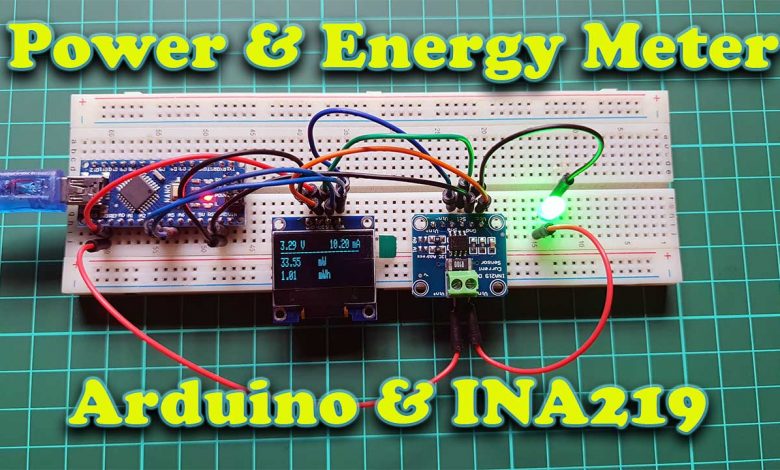
Overview: Arduino Power & Energy Meter
In this project, I’ll show you how to make an Arduino based power and energy meter that can measure current, power, and energy consumption using the INA219 current sensor and show it on an OLED display. You can see your voltage, current, power, and energy data on the OLED display.
The INA219 Current Sensor is an I2C-supported interface-based zero drift and bi-directional current/power monitoring module. It can measure the current, voltage, and power of a circuit. We can easily use INA219 Current Sensor with Arduino to measure current, and power, and it can also sense shunt voltage. This Sensor module is provided with 0.1 ohms, and a 1% shunt resistor to fulfill the requirement of current measurements. It can measure DC voltage up to +26V. There are so many other technical details we will learn later on the sub-topic.
Components Required
Following is the list of all the components required for making Arduino based Power and Energy meters using the INA219 sensor. All the components are available on amazon.
| S.N | Components Name | Quantity | |
|---|---|---|---|
| 1 | Arduino Nano | 1 | https://amzn.to/3Hf7zvN |
| 2 | 0.96" I2C OLED Display | 1 | https://amzn.to/3kvENyc |
| 3 | INA219 Current Sensor | 1 | https://amzn.to/3wAcuVv |
| 4 | Few jumpers wires | 20 | https://amzn.to/3klh0A4 |
*Please Note: These are affiliate links. I may make a commission if you buy the components through these links. I would appreciate your support in this way!
Technical Datasheet of the INA219 Voltage and Current Sensor
The following table shows the technical datasheet of the INA219 voltage and current sensor.
| Measurement Voltage | 0V…26V |
| Max Current | 3.2A |
| Max Power | 83W |
| Operation Voltage | 3V…5.5V |
| Communication Protocol | I2C |
The maximum voltage that can be measured with the INA219 sensor is 26V and the maximum current is 3.2A.
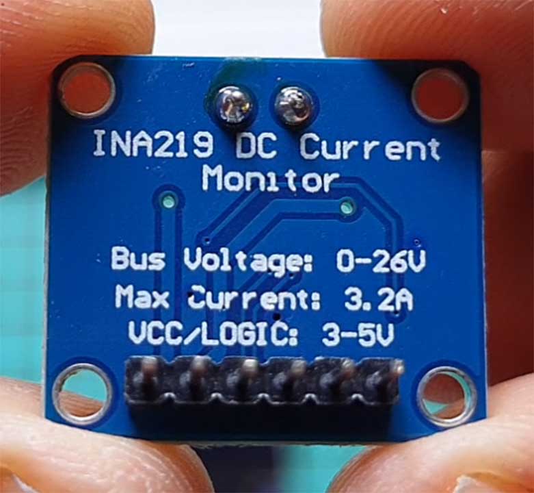
The operation voltage of the INA219 is between 3V and 5.5V. So, we can use different Arduino boards with an operating voltage of 5V or ESP8266 and ESP32 microcontroller with a lower operation voltage of 3.3V to read the voltage and current sensor values.
The sensor values are transferred via the I2C communication protocol between the INA219 module and the microcontroller.
How does the INA219 sensor work?
Before we start using INA219 sensor, we have to understand how this sensor works. To describe the functionality of the sensor, we go step by step over the simplified schematic of the INA219 which you see in the following picture.
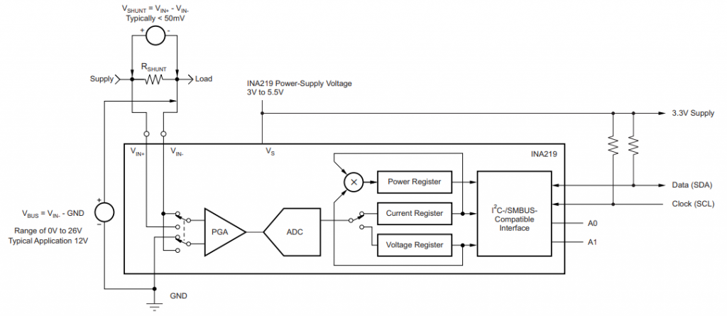
The INA219 sensor has a 2-pin screw-terminal, connected to the high side of the measuring in series, able to measure voltages up to 26V. The screw-term is connected to a 0.1Ω 1% sense shunt resistor in parallel. The INA219 measures two different voltages on the high side:
- V_shunt is the voltage drop across the shunt resistor.
- V_bus is the voltage from the negative pole with respect to the ground.
Both voltages are then forwarded to the Programmable Gain Amplifier (PGA) to increase the sensitivity of the measurement. The INA219 increases the full-scale range up to 2, 4, or 8 times (320mV). Also, the bus voltage measurements have two ranges: 16V and 32V.
After the sensitivity of the voltage measurement is increased, the current and also the power is calculated. The following picture shows how the calculation is done based on the shunt and bus voltage.
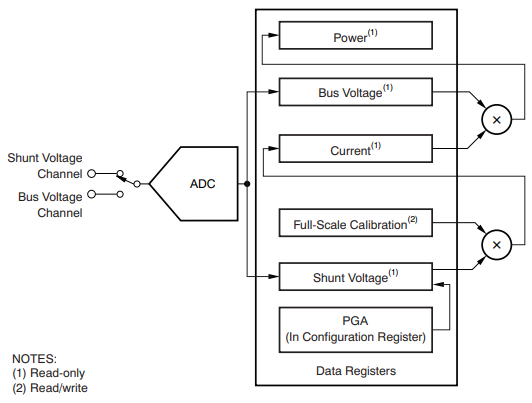
The current flow on the high side of the measurement is calculated by multiplying the shunt voltage with the calibrated resistance of the shunt resistor. Because the shunt resistor is 0.1Ω and the maximum shunt voltage at the scale of 8 is 320mV, the maximum current that can be measured is 320mV / 0.1Ω = 3.2A.
Then the power is calculated with this current multiplied by the bus voltage. Based on the maximum current of 3.2A and a maximum bus voltage of 26V, the INA219 can measure up to 3.2A * 26V = 83W of power.
Therefore the INA219 is able to provide four different measurements:
- Shunt voltage: voltage drop across the shunt resistor
- Bus voltage: total voltage seen by the circuit under test. (supply voltage – shunt voltage).
- Current: derived via Ohms Law from the measured shunt voltage
- Power: current multiplied by the bus voltage
Each of the measurements and calculations is stored in a register that is connected to the I2C interface to forward the values to the Arduino or ESP microcontroller.
Now we know the basic functionality of the INA219 voltage sensor but if you are interested in more details about the sensor. visit the product description.
INA219 connection with Arduino:
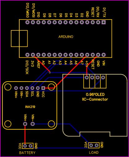
The wiring of the INA219 is shown in the following pictures for different Arduino. In my case, I powered the INA219 from the microcontroller with 5V but you can also use 3.3V instead. Also, you have to connect the clock (SCL) and data (SDA) pins for the I2C communication to send the information about voltage, current, and power from the INA219 to the microcontroller.
Now to connect the Arduino Nano with the INA219 current sensor & OLED Display we will perform the following steps:
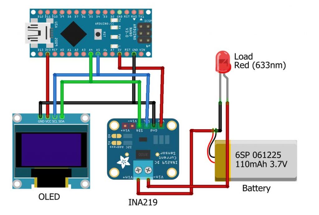
- Interface the SDA and SCL pins of the INA219 current sensor & OLED Display with the A4 & A5 pins of the Arduino Nano.
- Interface the VCC pin of the INA219 with 5V of the Arduino Nano.
- Similarly, the VCC pin of OLED is connected to the 3.3V pin of Arduino.
- Connect the ground pin of the INA219 current sensor & OLED with the ground of the Arduino.
- Connect the positive terminal of the battery to the Vin+ of the INA219 sensor.
- Now, Connect the cathode of the LED with the Negative terminal of battery and connect the anode of the LED with the Vin-
You can use power from arduino if don’t have battery to test this project.
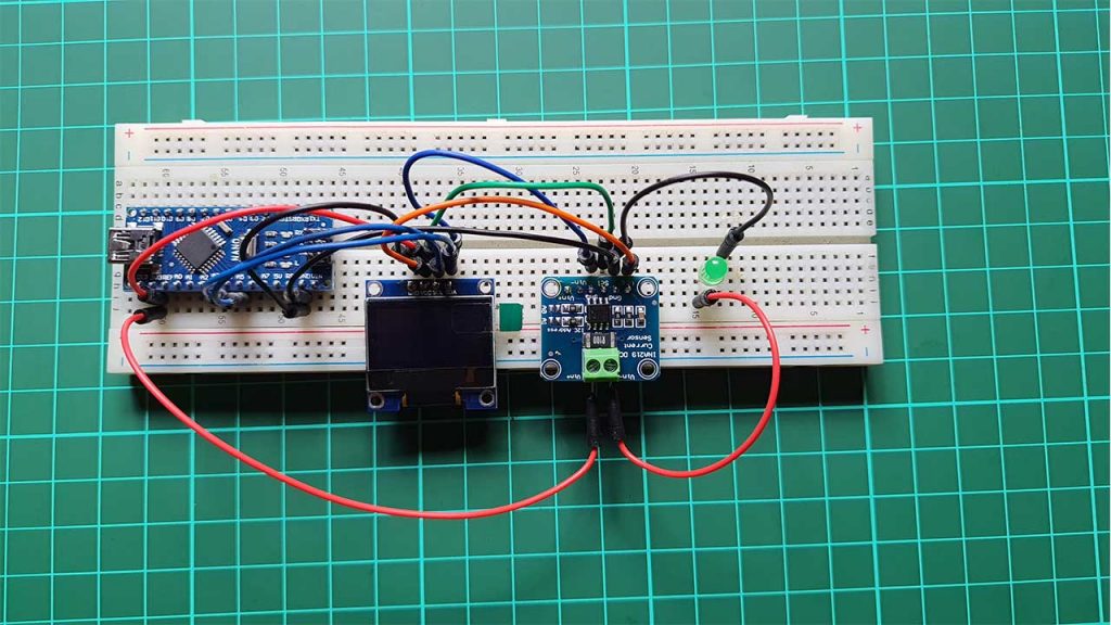
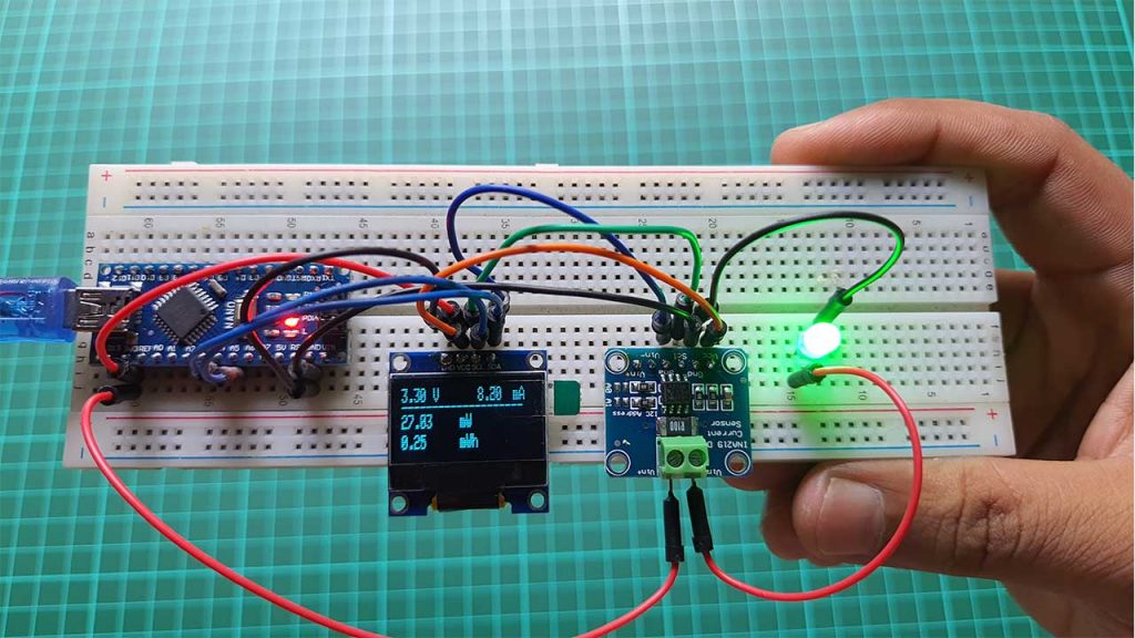
Now let’s take a look at the schematic I used for testing the INA219 module. I used an Arduino Nano for the controller and for the load I used one LED. To display the change of the current and voltage value I used this small OLED Display.
Project PCB Gerber File & PCB Ordering Online
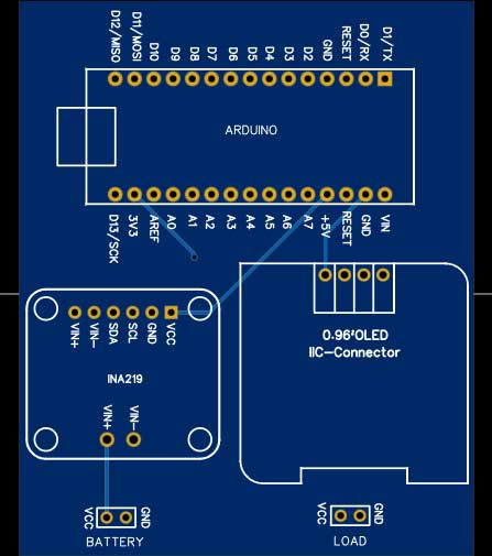
You can simply assemble the circuit on a breadboard. But To remove messy wiring and give a clean look, I designed a PCB prototype for this project. It is also helpful for troubleshooting without any errors. You can download the Gerber file of my PCB Design from the link attached below. The PCB looks like the image shown below.
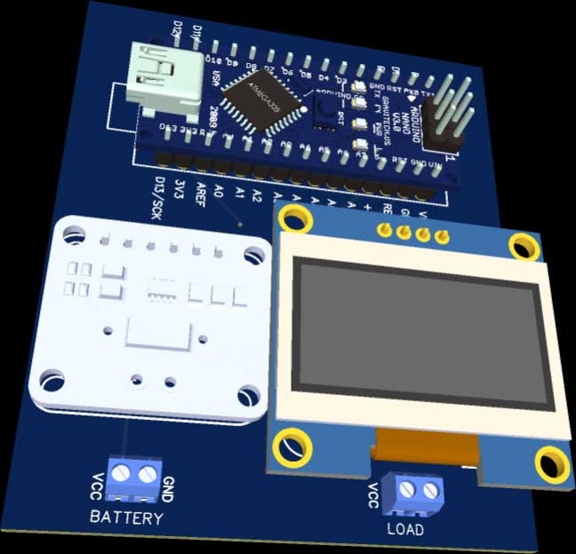
I provided the Gerber File for Arduino based Power & Energy Meter using INA219 Sensor PCB below.
You can simply download the Gerber File and order your custom PCB from PCBWay

Visit the PCBWay official website by clicking here: https://www.PCBWay.com/. Simply upload your Gerber File to the Website and place an order. I prefer PCBWay for ordering custom PCBs. PCBWay is a place that brings manufacturers and customers together. They have more than a decade of experience in this field of fabrication, prototyping, and assembling PCBs. PCBWay have proved their focus to their customers’ needs in terms of cost-effectiveness, delivery, and quality. And this can be proved by their outstanding customer reviews.
How to Find the INA219 I2C Address?
In order to communicate with the INA219 via I2C. We have to know the I2C address of the electrical device. Because each device gets its own unique address in an I2C network. The default I2C address of the INA219 sensor is 0x40 and is important for the later on Arduino programming.
If you are not sure if your sensor has the I2C address 0x40, I created an I2C scanner Code that requires no additional hardware and finds the address of all connected I2C devices. Just Upload this code to any microcontroller and open the serial monitor to see the I2C address of the connected devices.
// I2C address Scanner code

#include <Wire.h>


void setup()
{
  Wire.begin();

  Serial.begin(115200);
  while (!Serial);             // Leonardo: wait for serial monitor
  Serial.println("I2C Scanner");
}


void loop()
{
  byte error, address;
  int nDevices;

  Serial.println("Scanning...");

  nDevices = 0;
  for (address = 1; address < 127; address++ )
  {
    // The i2c_scanner uses the return value of
    // the Write.endTransmisstion to see if
    // a device did acknowledge to the address.
    Wire.beginTransmission(address);
    error = Wire.endTransmission();

    if (error == 0)
    {
      Serial.print("I2C device found at address 0x");
      if (address < 16)
        Serial.print("0");
      Serial.print(address, HEX);
      Serial.println("  !");

      nDevices++;
    }
    else if (error == 4)
    {
      Serial.print("Unknown error at address 0x");
      if (address < 16)
        Serial.print("0");
      Serial.println(address, HEX);
    }
  }
  if (nDevices == 0)
    Serial.println("No I2C devices found");
  else
    Serial.println("done");

  delay(5000);           // wait 5 seconds for next scan
}
But what do you do if you want to use two INA219 current sensors and read the values of both sensors with a single Arduino or ESP microcontroller? By default, both sensors have the I2C address 0x40. In order to read data from multiple sensors, the I2C address has to be unique. Therefore on the right side of the INA219, you see two different contact pairs next to two resistors. The following picture shows the contacts of the voltage and current sensor.
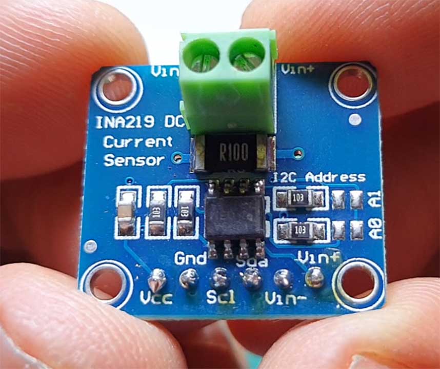
Depending on the contact you bridge by soldering the contacts, the I2C address changes. Therefore you can use up to four different INA219 boards in one I2C network. The following table shows the four different boards, their I2C address, and what contacts have to be bridged. The top contact is A1 and the bottom contact is A0.
| Board | I2C address | Contact to be bridged |
| 1 | 0X40 | No contacts bridged |
| 2 | 0X41 | Bridge A0 |
| 3 | 0X44 | Bridge A1 |
| 4 | 0X45 | Bridge A0 and A1 |
Arduino & INA219 Program Code
After we connected all parts let’s dive into the program code. To compile and upload this code you need to install the required libraries first.
Install Adafruit_INA219 and Adafruit_SSD1306 library in your Arduino IDE.
Source Code Program of Arduino based Power & Energy Meter using INA219 Sensor
#include <Wire.h>
#include <Adafruit_INA219.h>
#include <Adafruit_SSD1306.h>

#define SCREEN_WIDTH 128 // OLED display width, in pixels
#define SCREEN_HEIGHT 32 // OLED display height, in pixels
#define OLED_RESET     -1 // Reset pin # (or -1 if sharing Arduino reset pin)
#define SCREEN_ADDRESS 0x3C ///< See datasheet for Address; 0x3D for 128x64, 0x3C for 128x32
Adafruit_SSD1306 display(SCREEN_WIDTH, SCREEN_HEIGHT, &Wire, OLED_RESET);
Adafruit_INA219 ina219;

unsigned long previousMillis = 0;
unsigned long interval = 100;
  float shuntvoltage = 0;
  float busvoltage = 0;
  float current_mA = 0;
  float loadvoltage = 0;
  float power_mW = 0;
  float energy = 0;

void setup(void)
{
  Serial.begin(115200);
  while (!Serial) {
      // will pause Zero, Leonardo, etc until serial console opens
      delay(1);
  }

  uint32_t currentFrequency;

  Serial.println("Hello!");
  display.begin(SSD1306_SWITCHCAPVCC, 0x3C);
  display.clearDisplay();

  // Initialize the INA219.
  // By default the initialization will use the largest range (32V, 2A).  However
  // you can call a setCalibration function to change this range (see comments).
  if (! ina219.begin()) {
    Serial.println("Failed to find INA219 chip");
    while (1) { delay(10); }
  }
  // To use a slightly lower 32V, 1A range (higher precision on amps):
  //ina219.setCalibration_32V_1A();
  // Or to use a lower 16V, 400mA range (higher precision on volts and amps):
  //ina219.setCalibration_16V_400mA();

  Serial.println("Measuring voltage and current with INA219 ...");
}

void loop()
{
  unsigned long currentMillis = millis();
  if (currentMillis - previousMillis >= interval)
  {
    previousMillis = currentMillis;
    ina219values();
    displaydata();
  }
}


void ina219values()  {

  shuntvoltage = ina219.getShuntVoltage_mV();
  busvoltage = ina219.getBusVoltage_V();
  current_mA = ina219.getCurrent_mA();
  power_mW = ina219.getPower_mW();
  loadvoltage = busvoltage + (shuntvoltage / 1000);
  energy = energy + loadvoltage * current_mA / 3600;

  Serial.print("Bus Voltage:   "); Serial.print(busvoltage); Serial.println(" V");
  Serial.print("Shunt Voltage: "); Serial.print(shuntvoltage); Serial.println(" mV");
  Serial.print("Load Voltage:  "); Serial.print(loadvoltage); Serial.println(" V");
  Serial.print("Current:       "); Serial.print(current_mA); Serial.println(" mA");
  Serial.print("Power:         "); Serial.print(power_mW); Serial.println(" mW");
  Serial.println("");
}
void displaydata() {
  display.clearDisplay();
  display.setTextColor(WHITE);
  display.setTextSize(1);
  display.setCursor(0, 0);
  display.println(loadvoltage);
  display.setCursor(31, 0);
  display.println("V");
  display.setCursor(62, 0);
  display.setCursor(75, 0);
  display.println(current_mA);
  display.setCursor(110, 0);
  display.println("mA");
  display.setCursor(0, 6);
  display.println("--------------------");


  display.setCursor(0, 13);
  display.println(loadvoltage * current_mA);
  display.setCursor(57, 13);
  display.println("mW");
  display.setCursor(0, 23);
  display.println(energy);
  display.setCursor(57, 23);
  display.println("mWh");
  display.display();
}
Program Code Explanation
In the first part of the code, we include the Wire and Adafruit INA219 and Ardfruit SSD1306 library. The Wire library enables the microcontroller to use the I2C communication. Because the INA219 current and voltage sensor are connected to the microcontroller via I2C. The Adafruit INA219 library makes the handling of the sensor itself easier because we only need to use one function for each measurement. Then SSD1306 library is used for displaying the result on OLED Dispaly.
#include <Wire.h>
#include <Adafruit_INA219.h>
#include <Adafruit_SSD1306.h>
After the three libraries are included, OLED Display Width, Height, and Address is defined. Similarly the Adafruit INA219 object is created with the name ina219.
#define SCREEN_WIDTH 128 // OLED display width, in pixels
#define SCREEN_HEIGHT 32 // OLED display height, in pixels
#define OLED_RESET     -1 // Reset pin # (or -1 if sharing Arduino reset pin)
#define SCREEN_ADDRESS 0x3C ///< See datasheet for Address; 0x3D for 128x64, 0x3C for 128x32
Adafruit_SSD1306 display(SCREEN_WIDTH, SCREEN_HEIGHT, &Wire, OLED_RESET);
Adafruit_INA219 ina219;
Now we created float variables for each measurement that are all set to zero.
unsigned long previousMillis = 0;
unsigned long interval = 100;
  float shuntvoltage = 0;
  float busvoltage = 0;
  float current_mA = 0;
  float loadvoltage = 0;
  float power_mW = 0;
  float energy = 0;
In the setup function, we open the serial communication with the baud rate of 115200 because I want to display the measurements to the serial monitor of the Arduino IDE. Also with the while loop, we wait until the serial port is connected. Then I initiliaze the OLED Display with its I2C address.
void setup(void)
{
  Serial.begin(115200);
  while (!Serial) {
      // will pause Zero, Leonardo, etc until serial console opens
      delay(1);
  }

  uint32_t currentFrequency;

  Serial.println("Hello!");
  display.begin(SSD1306_SWITCHCAPVCC, 0x3C);
  display.clearDisplay();
In the second part of the setup function, the INA219 object is initialized with the begin function and if the object cannot be initialized, we know that something with the chip is wrong. Therefore we print this error message to the serial output.
 // Initialize the INA219.
  // By default the initialization will use the largest range (32V, 2A).  However
  // you can call a setCalibration function to change this range (see comments).
  if (! ina219.begin()) {
    Serial.println("Failed to find INA219 chip");
    while (1) { delay(10); }
  }
The loop function we start measuring the values and keep measurements to each variable declared earlier.
void ina219values()  {

  shuntvoltage = ina219.getShuntVoltage_mV();
  busvoltage = ina219.getBusVoltage_V();
  current_mA = ina219.getCurrent_mA();
  power_mW = ina219.getPower_mW();
  loadvoltage = busvoltage + (shuntvoltage / 1000);
  energy = energy + loadvoltage * current_mA / 3600;

  Serial.print("Bus Voltage:   "); Serial.print(busvoltage); Serial.println(" V");
  Serial.print("Shunt Voltage: "); Serial.print(shuntvoltage); Serial.println(" mV");
  Serial.print("Load Voltage:  "); Serial.print(loadvoltage); Serial.println(" V");
  Serial.print("Current:       "); Serial.print(current_mA); Serial.println(" mA");
  Serial.print("Power:         "); Serial.print(power_mW); Serial.println(" mW");
  Serial.println("");
}
Now every variable is filled by the get function of the Adafruit INA219 library but the load voltage is calculated by adding the shunt voltage to the bus voltage. The deviation with 1000 is only done to match the units.
- Shunt voltage measured in millivolt
- Bus voltage measured in volt
- Load voltage calculated in volt
- Current calculated in milliamps
- Power calculated in milliamps
Finally, we display all those calculated values on the OLED Display.
void displaydata() {
  display.clearDisplay();
  display.setTextColor(WHITE);
  display.setTextSize(1);
  display.setCursor(0, 0);
  display.println(loadvoltage);
  display.setCursor(31, 0);
  display.println("V");
  display.setCursor(62, 0);
  display.setCursor(75, 0);
  display.println(current_mA);
  display.setCursor(110, 0);
  display.println("mA");
  display.setCursor(0, 6);
  display.println("--------------------");


  display.setCursor(0, 13);
  display.println(loadvoltage * current_mA);
  display.setCursor(57, 13);
  display.println("mW");
  display.setCursor(0, 23);
  display.println(energy);
  display.setCursor(57, 23);
  display.println("mWh");
  display.display();
}
Conclusion
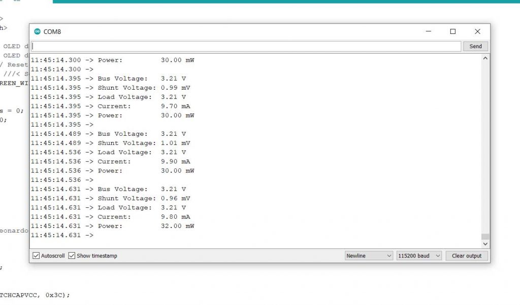
After successfully uploading the program code. You can open the serial monitor to check current, power, and energy consumption using the INA219 current sensor.
Similarly you can also see all the measured data on OLED Display as shown in the below image.
So, this is how we created Arduino based Power & Energy Meter using the INA219 Sensor. I hope this tutorial was helpful for you. Consider sharing this article if it helped you a lot.

Hi,
thanks for the tutorial. I have a question regarding the energy calculation.
Measurements are taken every 0.1 seconds :
unsigned long interval = 100;
The energy is continuously added here:
energy = energy + loadvoltage * current_mA / 3600;
However an hour should have 36000 0.1 seconds. Did I miss something here or would the energy calculation be for a measurement each second?
Also can you say how accurate a measurement each 100 milliseconds is? Everything happening in between the measurements can’t be noticed. Can the chip itself measure with a higher frequency and then just output an average?
Thanks and best regards
riag
the code is not running