IoT Smart Agriculture & Automatic Irrigation System with ESP8266
Smart Agriculture Monitoring & Auto Irrigation System using IoT
- Overview: IoT Based Smart Agriculture Monitoring & Irrigation System
- Components Required
- Circuit Diagram connection/Schematic
- Setting up Blynk IoT Cloud Dashboard
- Source Code/Program: ESP8266 IoT Agriculture
- Demonstration: IoT Smart Agriculture & Automatic Irrigation System with ESP8266
- Video Tutorial & Guide
- Conclusion
Overview: IoT Based Smart Agriculture Monitoring & Irrigation System
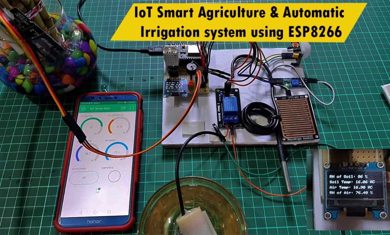
In this project, we will make IoT based smart agriculture monitoring and automatic irrigation system using ESP8266 NodeMCU. We will use multiple sensors like capacitive soil moisture sensor to measure moisture content present in the soil. DS18B20 waterproof temperature sensor to measure the temperature of the soil. We will also use the DHT22 humidity and temperature sensor to measure the air temperature and humidity.
Similarly, to monitor soil relative humidity, air temperature, soil temperature, and relative humidity of air we have used this small 0.96 inch OLED Display. A PIR motion sensor is used to detect the motion activity. maybe an animal or a human entering our farm.
Rain detector sensor to detect rain status. A 5 Volt buzzer for the Alert system and a 5-volt power relay to control the water pump, whenever a low quantity of moisture is detected in the soil.
The motor automatically turns ON and hence the irrigation is done automatically. Once the soil becomes wet the motor turns OFF automatically. All these happenings can be monitored and controlled remotely using the ESP8266 NodeMCU board and Blynk IoT Platform from any part of the world.
Also, learn to Interface:
Components Required
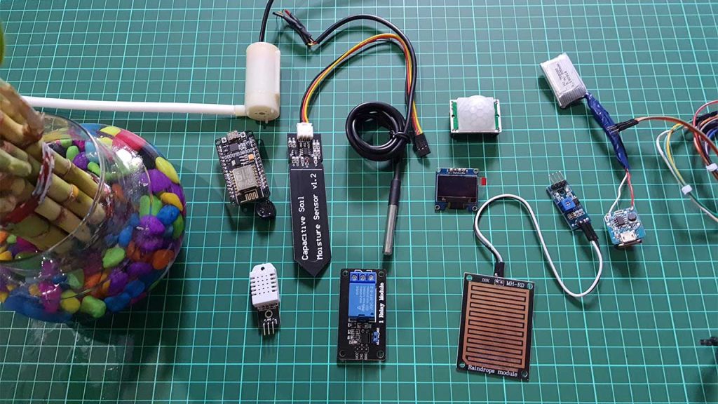
For this project, we need a NodeMCU ESP8266 board, a capacitive soil moisture sensor, DS18B20 waterproof temperature sensor, DHT22 Temperature, and Humidity sensor, PIR Motion sensor, Rain detector sensor, 0.96-inch OLED display, 5 Volt single channel relay module, a buzzer, and a 5-volt dc pump motor. The motor is used for drawing water from the inlet and throwing water through the outlet. A pipe can be connected to it. You can purchase all these components from the Amazon link provided below.
| S.N | Components Name | Quantity | |
|---|---|---|---|
| 1 | NodeMCU ESP8266-12E Board | 1 | https://amzn.to/3sCrEbj |
| 2 | Capacitive Soil Moisture Sensor | 1 | https://amzn.to/3nyL9y7 |
| 3 | DHT22 Temperature & Humidity Sensor | 1 | https://amzn.to/32VEw1X |
| 4 | DS18B20 waterproof Temperature Sensor | 1 | https://amzn.to/33EkMQq |
| 5 | 0.96" I2C OLED Display | 1 | https://amzn.to/3kvENyc |
| 6 | PIR Motion Sensor | 1 | https://amzn.to/3navcxS |
| 7 | 5V Single-Channel Relay Module | 1 | https://amzn.to/3tBoAg2 |
| 8 | 5V Small Buzzer | 1 | https://amzn.to/3I5qhXl |
| 9 | Rain Detector Sensor | 1 | https://amzn.to/3frrDPG |
| 10 | Few jumpers wires | 20 | https://amzn.to/3klh0A4 |
| 11 | Breadboard | 1 | https://amzn.to/3H2tbeQ |
Circuit Diagram connection/Schematic
Here is the schematic of this project. I used fritzing software to design this circuit diagram.
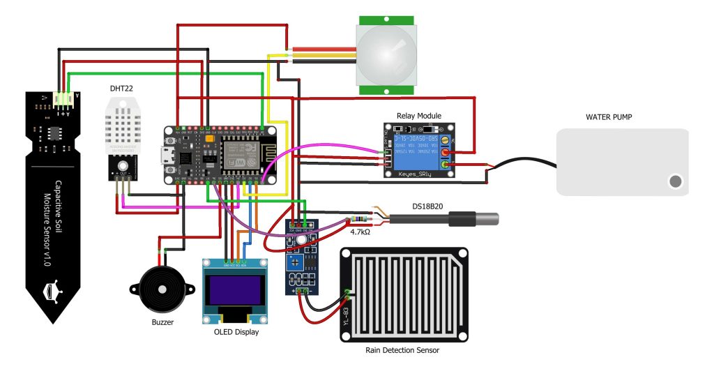
Connect the soil moisture sensor to the A0 pin of Nodemcu and DHT22 to the D4 Pin. DS18B20 temperature sensor to D6 pin. PIR Motion Sensor to D3 pin. Buzzer to D5 pin and Rain Sensor to D7 Pin of NodeMCU. The motor is connected to Relay. To control the relay, we use the D0 Pin of NodeMCU. Connect the OLED display to the I2C pin (D1 & D2 pin) of NodeMCU. You can power the DS18B20 sensor, PIR Sensor, Water Motor, buzzer, and Relay using the 5V pin of NodeMCU. The DHT22 Sensor, Capacitive Soil Moisture Sensor, and OLED Display require a 3.3V Supply only.
So, assemble all the components according to the circuit diagram.
Project PCB Gerber File & PCB Ordering Online
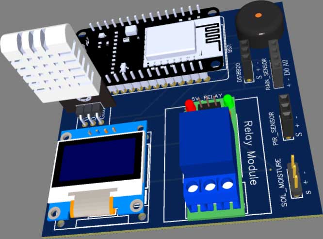
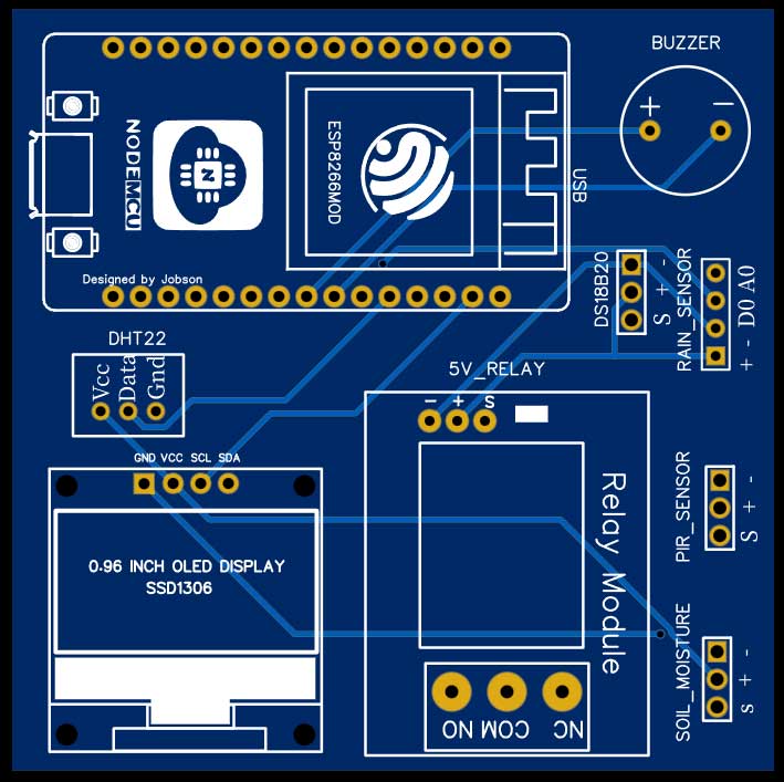
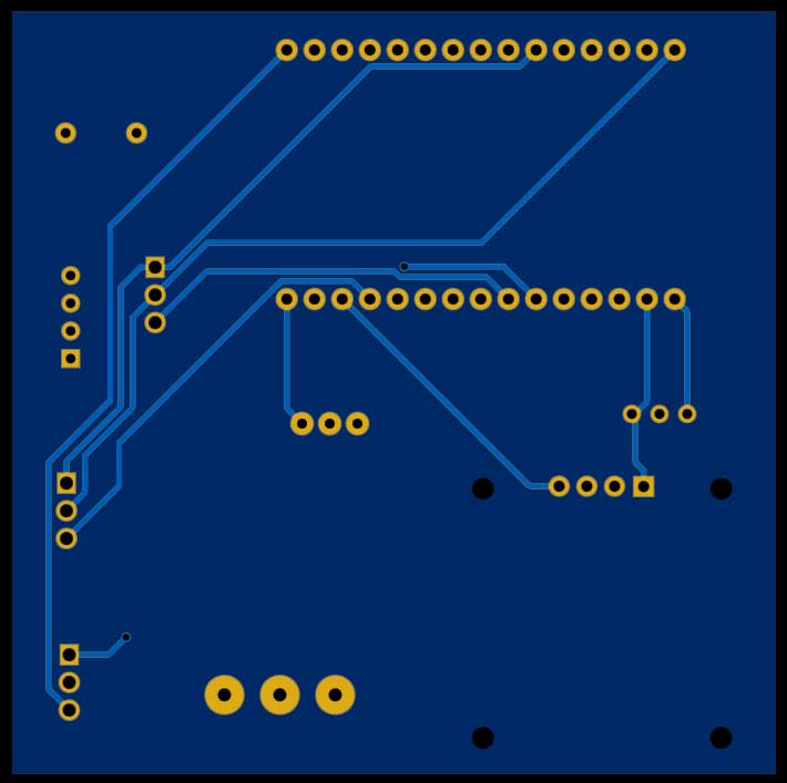
You can simply assemble the circuit on a breadboard. But To remove messy wiring and give a clean look, I designed a PCB prototype for this project. It is also helpful for troubleshooting without any errors. You can download the Gerber file of my PCB Design from the link attached below. The PCB looks like the image shown below.
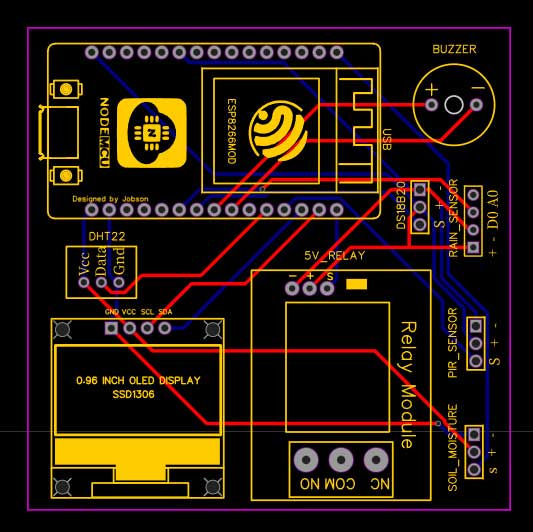
I provided the Gerber File for IoT Smart Agriculture & Automatic Irrigation System with ESP8266 PCB below.
You can simply download the Gerber File and order your custom PCB from PCBWay

Visit the PCBWay official website by clicking here: https://www.PCBWay.com/. Simply upload your Gerber File to the Website and place an order. I prefer PCBWay for ordering custom PCBs. PCBWay is a place that brings manufacturers and customers together. They have more than a decade of experience in this field of fabrication and prototyping and assembling of PCBs. PCBWay have proved their focus to their customers’ needs in terms of cost-effectiveness, delivery, and quality. And this can be proved by their outstanding customer reviews.
Setting up Blynk IoT Cloud Dashboard
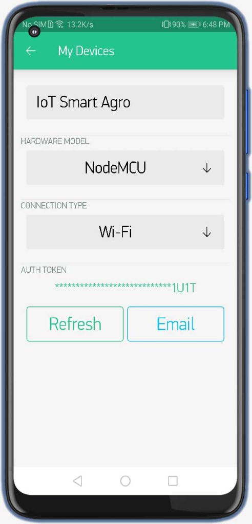
First of all, download the Blynk application from the play store or App store. Signup/sign in using your credentials. Now, click on open and create a new project.
Provide the name of your project I am giving “IoT smart Agro”. Select the NodeMCU board, Select the connection type as Wi-Fi, and click on create now button. The authentication token will be sent to your email address. We will need it later on, in the programming part.
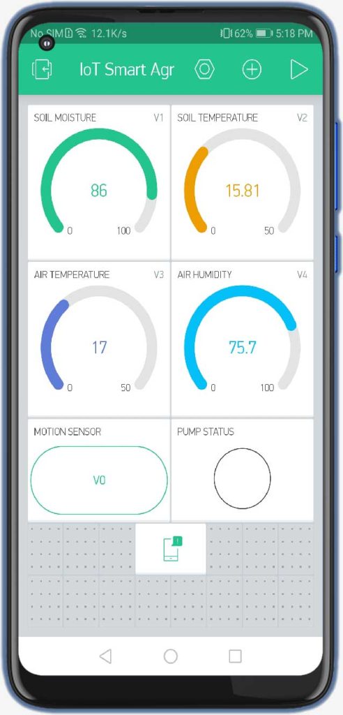
First, we will add a gauge. So select the gauge, click on it and give the name soil moisture.
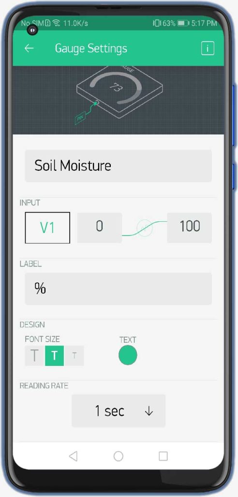
Now select the input pin as virtual pin V1 and Change the label to “%”. You can change the color of your gauge and also change the refresh rate to 1 second.
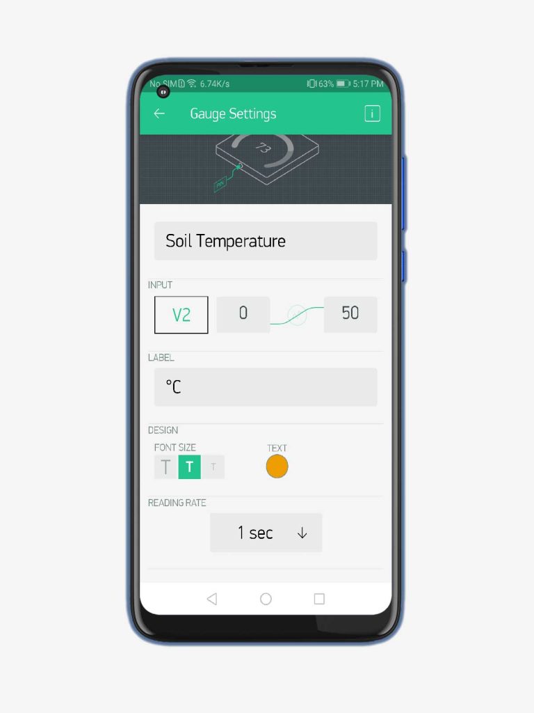
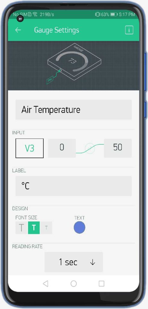
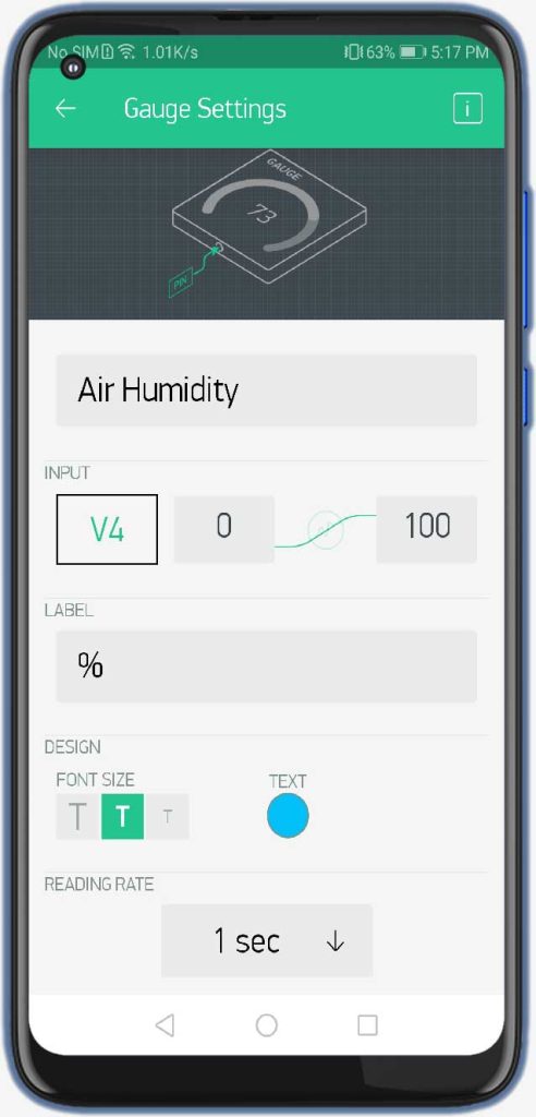
Similarly, add a gauge for soil temperature configured to V2 Pin. Air Temperature Gauge configured to V3 pin. and Air Humidity Configured to V4 Pin respectively.
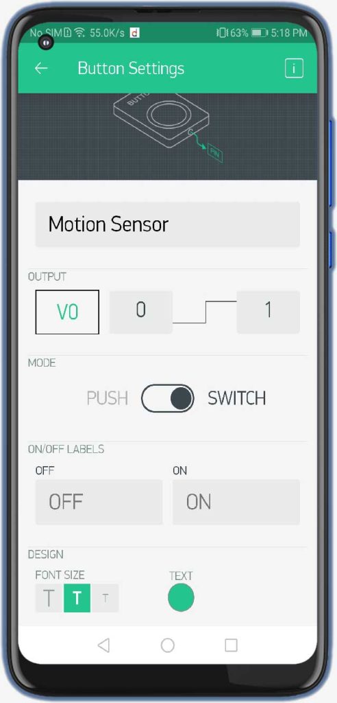
Now we’ll add a button, now open this button and we’ll select virtual pin V0 for it. and it will be for the PIR motion sensor. we’ll select the mode to switch.
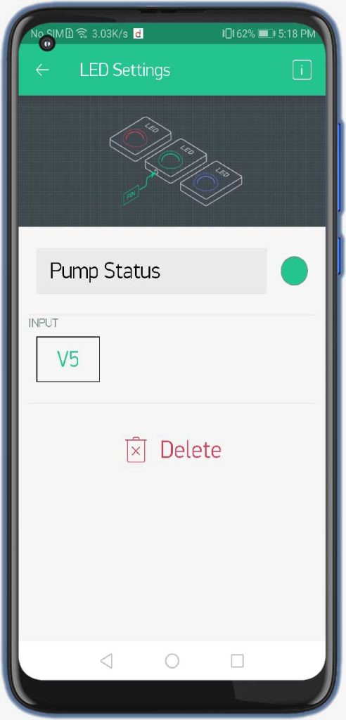
Here we will add LED for Pump status. The LED is configured to Virtual Pin V5. Finally, select the notification widget. It receives notifications sent from nodemcu for the alert system.
So, this is our newly configured Blynk IoT Dashboard for Monitoring sensor data online.
Source Code/Program: ESP8266 IoT Agriculture
Now let’s see the code part. We need a few libraries to compile and upload this code. You can install them from Arduino IDE Library Manager.
#define BLYNK_PRINT Serial
#include <SPI.h>
#include <ESP8266WiFi.h>
#include <BlynkSimpleEsp8266.h>
#include <SPI.h>
#include <Wire.h>
#include <OneWire.h>
#include <DallasTemperature.h>
#include <Adafruit_Sensor.h>
#include <Adafruit_GFX.h>
#include <Adafruit_SSD1306.h>
#include <DHT.h>
The code is pretty simple and easy to understand but you need to make some changes in a few parameters, for example, change the blynk authentication token, WiFi SSID, and password. Here we are sending the data to the Blynk IoT server.
char auth[] = "2P1bADi-_kVvS0TBpsWB5xEFgyUU1U1T";       //Authentication code sent by Blynk
char ssid[] = "Alsan Air WiFi";                        //WiFi SSID
char pass[] = "The IoT Projects";                //WiFi Password
Here we have defined an OLED Display I2C address and all the connection pins of sensors, relay, and buzzer.
#define SCREEN_WIDTH 128 // OLED display width, in pixels
#define SCREEN_HEIGHT 64 // OLED display height, in pixels
#define OLED_RESET -1 // Reset pin # (or -1 if sharing Arduino reset pin)
Adafruit_SSD1306 display(SCREEN_WIDTH, SCREEN_HEIGHT, &Wire, OLED_RESET);
#define DHTPIN D4          //pin where the dht11 is connected
DHT dht(DHTPIN, DHT22);
#define ONE_WIRE_BUS D6
OneWire oneWire(ONE_WIRE_BUS);
DallasTemperature sensors(&oneWire);

#define buzzer D5 //Buzzer Pin D5
#define rainPin D7
int rainState = 0;
int lastRainState = 0;
const int AirValue = 590;   //you need to replace this value with Value_1
const int WaterValue = 300;  //you need to replace this value with Value_2
const int SensorPin = A0;
int soilMoistureValue = 0;
int soilmoisturepercent = 0;
int relay = D0;


#define pirPin D3
int pirValue;
int pinValue;
The most important part of this code is the calibration of the Soil Moisture Sensor Value like AirValue and WaterValue.
const int AirValue = 590;   //you need to replace this value with Value_1
const int WaterValue = 300;  //you need to replace this value with Value_2
You need to upload this code first and read the value when the sensor is in Air and When the sensor dipped into the water.
Here we read the value from blynk from virtual pin V0 which is configured to PIR Motion sensor.
//Read value from blynk
BLYNK_WRITE(V0)
{
  pinValue = param.asInt();
}
In the setup part, we initialize all the sensors and set up the connection to the blynk cloud.
  Serial.begin(115200);
  delay(100);
  Blynk.begin(auth, ssid, pass);
  display.begin(SSD1306_SWITCHCAPVCC, 0x3C); //initialize with the I2C addr 0x3C (128x64)
  display.clearDisplay();
  pinMode(relay, OUTPUT);
  pinMode(buzzer, OUTPUT);
  sensors.begin(); // Dallas temperature
  dht.begin();
getPirValue reads the PIR digital pin and sends a notification if motion is detected.
void getPirValue(void)        //Get PIR Data
{
  pirValue = digitalRead(pirPin);
  if (pirValue)
  {
    Serial.println("Motion detected");
    Blynk.notify("Motion detected in your farm") ;
  }
}
In the loop section, we retrieve the value of air temperature and humidity and soil temperature.
  float h = dht.readHumidity();
  float t = dht.readTemperature();
  sensors.requestTemperatures();
  float temp = sensors.getTempCByIndex(0);

  Serial.print("Soil Temperature: ");
  Serial.println(temp);
  Serial.print("Temperature: ");
  Serial.println(t);
  Serial.print("Humidity: ");
  Serial.println(h);

  Blynk.virtualWrite(V3, t);  //V3 is for Temperature
  Blynk.virtualWrite(V4, h);  //V4 is for Humidity
  Blynk.virtualWrite(V2, temp); //Dallas Temperature
Similarly, we are reading the soil moisture data from the soil moisture sensor and converting it into percentages using a map function.
  soilMoistureValue = analogRead(SensorPin);  //put Sensor insert into soil
  Serial.println(soilMoistureValue);

  soilmoisturepercent = map(soilMoistureValue, AirValue, WaterValue, 0, 100);

  Blynk.virtualWrite(V1, soilmoisturepercent); //Soil Moisture sensor
Here, we are sending these parameters to the blynk server using virtual pins. We’ll also display the values on an OLED Display using some inbuilt library function.
  if (soilmoisturepercent > 100)
  {
    Serial.println("100 %");
    delay(1500);
    display.clearDisplay();

    // display Soil temperature
    display.setTextColor(WHITE);
    display.setTextSize(1);
    display.setCursor(0, 5);
    display.print("RH of Soil: ");
    display.print("100");
    display.print(" %");

    // display Air temperature
    display.setCursor(0, 20);
    display.print("Soil Temp: ");
    display.print(temp);
    display.print(" ");
    display.cp437(true);
    display.write(167);
    display.print("C");

    // display relative humidity of Soil
    display.setCursor(0, 35);
    display.print("Air Temp: ");
    display.print(t);
    display.print(" ");
    display.cp437(true);
    display.write(167);
    display.print("C");

    // display relative humidity of Air
    display.setCursor(0, 50);
    display.print("RH of Air: ");
    display.print(h);
    display.print(" %");

    display.display();
    delay(1500);
  }
  else if (soilmoisturepercent < 0)
  {
    Serial.println("0 %");
    delay(1500);
    display.clearDisplay();

    // display Soil temperature
    display.setTextColor(WHITE);
    display.setTextSize(1);
    display.setCursor(0, 5);
    display.print("RH of Soil: ");
    display.print("0");
    display.print(" %");

    // display Air temperature
    display.setCursor(0, 20);
    display.print("Soil Temp: ");
    display.print(temp);
    display.print(" ");
    display.cp437(true);
    display.write(167);
    display.print("C");

    // display relative humidity of Soil
    display.setCursor(0, 35);
    display.print("Air Temp: ");
    display.print(t);
    display.print(" ");
    display.cp437(true);
    display.write(167);
    display.print("C");

    // display relative humidity of Air
    display.setCursor(0, 50);
    display.print("RH of Air: ");
    display.print(h);
    display.print(" %");

    display.display();
    delay(1500);
  }
  else if (soilmoisturepercent >= 0 && soilmoisturepercent <= 100)
  {
    Serial.print(soilmoisturepercent);
    Serial.println("%");
    delay(1500);
    display.clearDisplay();

    // display Soil temperature
    display.setTextColor(WHITE);
    display.setTextSize(1);
    display.setCursor(0, 5);
    display.print("RH of Soil: ");
    display.print(soilmoisturepercent);
    display.print(" %");

    // display Air temperature
    display.setCursor(0, 20);
    display.print("Soil Temp: ");
    display.print(temp);
    display.print(" ");
    display.cp437(true);
    display.write(167);
    display.print("C");

    // display relative humidity of Soil
    display.setCursor(0, 35);
    display.print("Air Temp: ");
    display.print(t);
    display.print(" ");
    display.cp437(true);
    display.write(167);
    display.print("C");

    // display relative humidity of Air
    display.setCursor(0, 50);
    display.print("RH of Air: ");
    display.print(h);
    display.print(" %");

    display.display();
    delay(1500);
These lines are for turning ON and OFF motors when a particular result is achieved. I have defined 30 as a threshold value. you can use your own depending upon the requirements. IF the soil moisture is below the threshold value. Blynk notification is sent to the mobile phone. Buzzer Alarms you locally when the relative humidity of soil is low.
  if (soilmoisturepercent >= 0 && soilmoisturepercent <= 30)
  {
    Serial.println("needs water, send notification");
    //send notification
    Blynk.notify("Plants need water... Pump is activated") ;
    digitalWrite(relay, LOW);
    digitalWrite(buzzer, HIGH);
    Serial.println("Motor is ON");
    WidgetLED PumpLed(V5);
    PumpLed.on();
    delay(1000);
  }
  else if (soilmoisturepercent > 30 && soilmoisturepercent <= 100)
  {
    Serial.println("Soil Moisture level looks good...");
    digitalWrite(relay, HIGH);
    digitalWrite(buzzer, LOW);
    Serial.println("Motor is OFF");
    WidgetLED PumpLed(V5);
    PumpLed.off();
    delay(1000);
  }
This code helps to detect rain and notifies you when rainfall occurs.
  rainState = digitalRead(rainPin);
  Serial.println(rainState);

  if (rainState == 0 && lastRainState == 0) {
    Serial.println("It's Raining outside!");
    Blynk.notify("It's Raining outside!") ;
    lastRainState = 1;
    delay(1000);
    //send notification

  }
  else if (rainState == 0 && lastRainState == 1) {
    delay(1000);
  }
  else {
    Serial.println("No Rains...");
    lastRainState = 0;
    delay(1000);
  }
Final Program Code
Copy this IoT based Smart Agriculture monitoring & Automatic Irrigation System with ESP8266 Program code and Paste it on your Arduino IDE.
// Blynk IOT Smart Agriculture Monitoring System

#define BLYNK_PRINT Serial
#include <SPI.h>
#include <ESP8266WiFi.h>
#include <BlynkSimpleEsp8266.h>
#include <SPI.h>
#include <Wire.h>
#include <OneWire.h>
#include <DallasTemperature.h>
#include <Adafruit_Sensor.h>
#include <Adafruit_GFX.h>
#include <Adafruit_SSD1306.h>
#include <DHT.h>  // Including library for dht

char auth[] = "2P1bADi-_kVvS0TBpsWB5xEFgyUU1U1T";       //Authentication code sent by Blynk
char ssid[] = "Alsan Air WiFi";                        //WiFi SSID
char pass[] = "The IoT Projects";                //WiFi Password

#define SCREEN_WIDTH 128 // OLED display width, in pixels
#define SCREEN_HEIGHT 64 // OLED display height, in pixels
#define OLED_RESET -1 // Reset pin # (or -1 if sharing Arduino reset pin)
Adafruit_SSD1306 display(SCREEN_WIDTH, SCREEN_HEIGHT, &Wire, OLED_RESET);

#define DHTPIN D4          //pin where the dht11 is connected
DHT dht(DHTPIN, DHT22);
#define ONE_WIRE_BUS D6
OneWire oneWire(ONE_WIRE_BUS);
DallasTemperature sensors(&oneWire);

#define buzzer D5 //Buzzer Pin D5
#define rainPin D7
int rainState = 0;
int lastRainState = 0;
const int AirValue = 590;   //you need to replace this value with Value_1
const int WaterValue = 300;  //you need to replace this value with Value_2
const int SensorPin = A0;
int soilMoistureValue = 0;
int soilmoisturepercent = 0;
int relay = D0;


#define pirPin D3
int pirValue;
int pinValue;

//Read value from blynk
BLYNK_WRITE(V0)
{
  pinValue = param.asInt();
}


void setup()
{
  Serial.begin(115200);
  delay(100);
  Blynk.begin(auth, ssid, pass);
  display.begin(SSD1306_SWITCHCAPVCC, 0x3C); //initialize with the I2C addr 0x3C (128x64)
  display.clearDisplay();
  pinMode(relay, OUTPUT);
  pinMode(buzzer, OUTPUT);
  sensors.begin(); // Dallas temperature
  dht.begin();
}

void getPirValue(void)        //Get PIR Data
{
  pirValue = digitalRead(pirPin);
  if (pirValue)
  {
    Serial.println("Motion detected");
    Blynk.notify("Motion detected in your farm") ;
  }
}

void loop() {
  Blynk.run();
  float h = dht.readHumidity();
  float t = dht.readTemperature();
  sensors.requestTemperatures();
  float temp = sensors.getTempCByIndex(0);

  Serial.print("Soil Temperature: ");
  Serial.println(temp);
  Serial.print("Temperature: ");
  Serial.println(t);
  Serial.print("Humidity: ");
  Serial.println(h);

  Blynk.virtualWrite(V3, t);  //V3 is for Temperature
  Blynk.virtualWrite(V4, h);  //V4 is for Humidity
  Blynk.virtualWrite(V2, temp); //Dallas Temperature

  soilMoistureValue = analogRead(SensorPin);  //put Sensor insert into soil
  Serial.println(soilMoistureValue);

  soilmoisturepercent = map(soilMoistureValue, AirValue, WaterValue, 0, 100);

  Blynk.virtualWrite(V1, soilmoisturepercent); //Soil Moisture sensor

  if (soilmoisturepercent > 100)
  {
    Serial.println("100 %");
    delay(1500);
    display.clearDisplay();

    // display Soil temperature
    display.setTextColor(WHITE);
    display.setTextSize(1);
    display.setCursor(0, 5);
    display.print("RH of Soil: ");
    display.print("100");
    display.print(" %");

    // display Air temperature
    display.setCursor(0, 20);
    display.print("Soil Temp: ");
    display.print(temp);
    display.print(" ");
    display.cp437(true);
    display.write(167);
    display.print("C");

    // display relative humidity of Soil
    display.setCursor(0, 35);
    display.print("Air Temp: ");
    display.print(t);
    display.print(" ");
    display.cp437(true);
    display.write(167);
    display.print("C");

    // display relative humidity of Air
    display.setCursor(0, 50);
    display.print("RH of Air: ");
    display.print(h);
    display.print(" %");

    display.display();
    delay(1500);
  }
  else if (soilmoisturepercent < 0)
  {
    Serial.println("0 %");
    delay(1500);
    display.clearDisplay();

    // display Soil temperature
    display.setTextColor(WHITE);
    display.setTextSize(1);
    display.setCursor(0, 5);
    display.print("RH of Soil: ");
    display.print("0");
    display.print(" %");

    // display Air temperature
    display.setCursor(0, 20);
    display.print("Soil Temp: ");
    display.print(temp);
    display.print(" ");
    display.cp437(true);
    display.write(167);
    display.print("C");

    // display relative humidity of Soil
    display.setCursor(0, 35);
    display.print("Air Temp: ");
    display.print(t);
    display.print(" ");
    display.cp437(true);
    display.write(167);
    display.print("C");

    // display relative humidity of Air
    display.setCursor(0, 50);
    display.print("RH of Air: ");
    display.print(h);
    display.print(" %");

    display.display();
    delay(1500);
  }
  else if (soilmoisturepercent >= 0 && soilmoisturepercent <= 100)
  {
    Serial.print(soilmoisturepercent);
    Serial.println("%");
    delay(1500);
    display.clearDisplay();

    // display Soil temperature
    display.setTextColor(WHITE);
    display.setTextSize(1);
    display.setCursor(0, 5);
    display.print("RH of Soil: ");
    display.print(soilmoisturepercent);
    display.print(" %");

    // display Air temperature
    display.setCursor(0, 20);
    display.print("Soil Temp: ");
    display.print(temp);
    display.print(" ");
    display.cp437(true);
    display.write(167);
    display.print("C");

    // display relative humidity of Soil
    display.setCursor(0, 35);
    display.print("Air Temp: ");
    display.print(t);
    display.print(" ");
    display.cp437(true);
    display.write(167);
    display.print("C");

    // display relative humidity of Air
    display.setCursor(0, 50);
    display.print("RH of Air: ");
    display.print(h);
    display.print(" %");

    display.display();
    delay(1500);
  }
  if (soilmoisturepercent >= 0 && soilmoisturepercent <= 30)
  {
    Serial.println("needs water, send notification");
    //send notification
    Blynk.notify("Plants need water... Pump is activated") ;
    digitalWrite(relay, LOW);
    digitalWrite(buzzer, HIGH);
    Serial.println("Motor is ON");
    WidgetLED PumpLed(V5);
    PumpLed.on();
    delay(1000);
  }
  else if (soilmoisturepercent > 30 && soilmoisturepercent <= 100)
  {
    Serial.println("Soil Moisture level looks good...");
    digitalWrite(relay, HIGH);
    digitalWrite(buzzer, LOW);
    Serial.println("Motor is OFF");
    WidgetLED PumpLed(V5);
    PumpLed.off();
    delay(1000);
  }

  rainState = digitalRead(rainPin);
  Serial.println(rainState);

  if (rainState == 0 && lastRainState == 0) {
    Serial.println("It's Raining outside!");
    Blynk.notify("It's Raining outside!") ;
    lastRainState = 1;
    delay(1000);
    //send notification

  }
  else if (rainState == 0 && lastRainState == 1) {
    delay(1000);
  }
  else {
    Serial.println("No Rains...");
    lastRainState = 0;
    delay(1000);
  }

  if (pinValue == HIGH)
  {
    getPirValue();
  }
  delay(100);
}
Now it’s time to upload the code. Make sure you remove the D3 pin connected to the PIR sensor while uploading the code. Select your NodeMCU 12E board from the Tools menu and also select the correct COM port. Then click on this little upload button.
It takes some time to compile & upload code to the board. After successful upload of the code, you can open the serial monitor at the baud rate of 115200.
Demonstration: IoT Smart Agriculture & Automatic Irrigation System with ESP8266
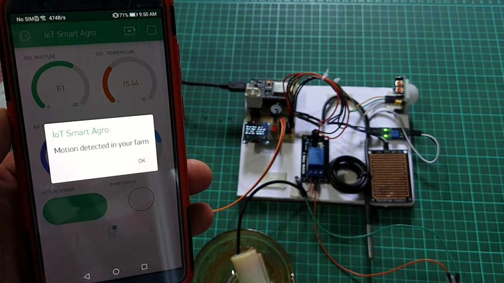
So now I have powered the complete system. This little OLED Display displays the Relative Humidity of Soil, Soil Temperature, Air Temperature, and Relative Humidity of Air. Whereas in the Blynk application you can see the soil moisture sensor readings. You can see the temperature of soil and air. Similarly, you can also see the relative humidity of Air. Then you will find an ON/OFF button for the PIR motion sensor. Then we have a LED status for the Water Pump.
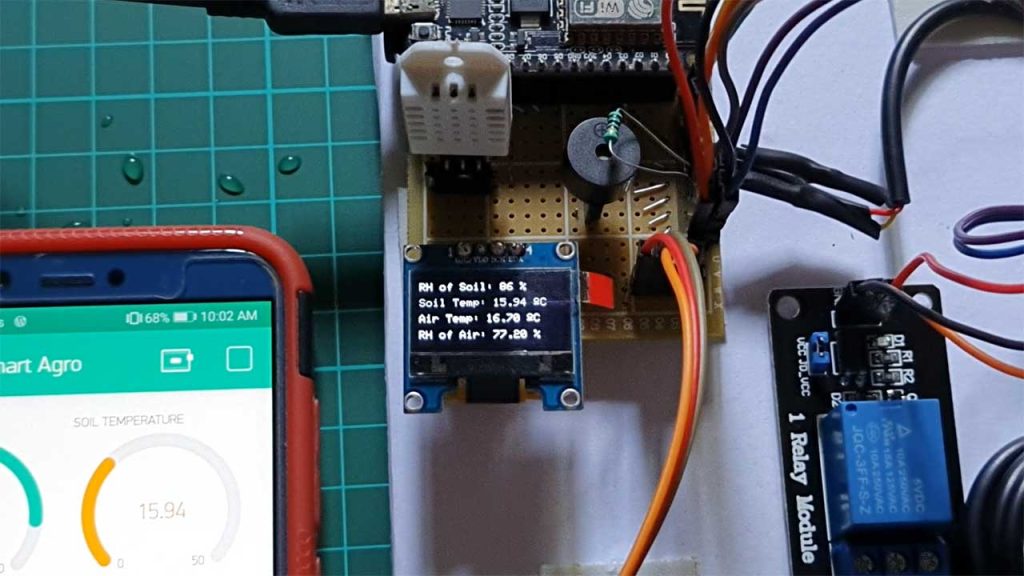
Now first we will test the soil moisture sensor. Here I am taking this little lucky bamboo plant pot to test this soil moisture sensor. Let me dip the sensor inside the water so you can see the reading Increasing. So, when I remove this sensor from here you can see the percentage decreasing.
As the soil moisture decreases, alarms get activated and the water pump is turned automatically. You can also see the pump LED glowing on the blynk app.
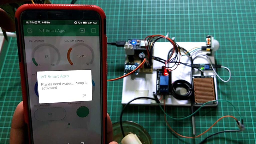
I have also got a message to water my plants because the sensor was dry and it was not in the water.
Now let’s test this rain detector sensor. Just pour some water into the sensor. As you can see I’ve got a message that it’s raining.
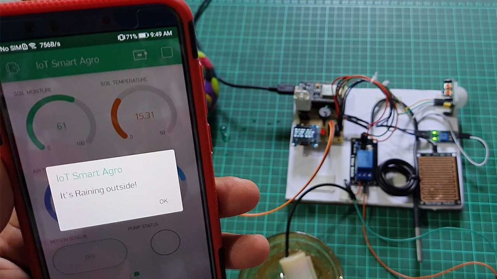
You can see a PIR motion sensor over here. it is right now OFF. I will turn it ON. So I’ve turned ON the PIR motion sensor. When I do any movement in front of it. It will detect motion and a message will be sent to our smartphone.
Video Tutorial & Guide
Conclusion
This tutorial shows you how to make an IoT Smart Agriculture & Automatic Irrigation System with ESP8266 & Blynk IoT Cloud. I hope this tutorial was interesting to you. If you need any type of help related to this project, then let me know in the comment section below.

Not sure why the 4.7k ohm resistor was not placed on the circuit board. Also, the relay pins do not align on the circuit board.
Very informative post. Agriculture is an important part of our life. There are many products & devices existing in the market which help in the agriculture industry. One is Wifi humidity sensors that help in a measure the humidity level in the agriculture industry. UbiBot provides a product that has the feature of tracking the history of the growing environment and even history reports can be downloaded for analysis, that is WS1 & WS1 Pro Environmental Monitoring device.
Thanks for sharing this amazing & helpful post with us.
Hallo Alsan
i love you project “IoT Smart Agriculture & Automatic Irrigation System with ESP8266”
but i have a problem with the sensor PIR Motion Sensor to D3 pin
i get all the time message “Motion detected in your farm”
Have you a ide why ?
i have add the code i use
BR Bjarne Arkevall
How to add events in blynk.console could you please tell me
Where must i connect the 4,7k resistance on DS18B20 ?
It is not clear on the draaiing.
The yellow cable is not connected.
Please, help me….
Thanks, please can I replace the OLED display with LCD (16×2)
Thank you for your project, is it possible to use esp 32 instead of esp 8266? i need same irrigation system with 30 nos moisture sensor, is it possible?
I tried to buy all of component from amazon, unfortunately none of parts above are available.
Thanking you
HII
have you made this?
Compilation error: ‘class BlynkWifi’ has no member named ‘notify’
having error withh this line kindly help
Compilation error: ‘class BlynkWifi’ has no member named ‘notify’
How do I resolve this issue?