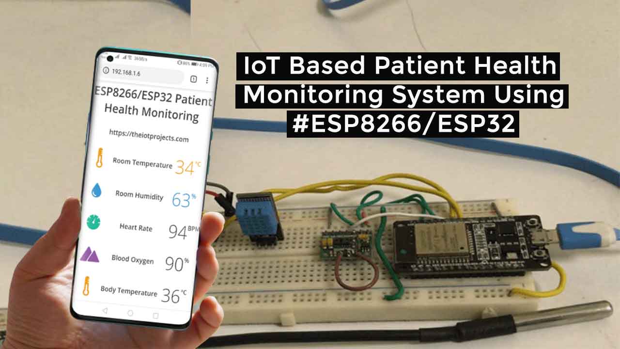
Today’s project is all about IoT Based Patient Health Monitoring System on ESP8266/ESP32 using MAX30100/102 Pulse Oximeter, DS18B20 temperature, and DHT11 Humidity & Temperature sensors. This system will Monitor the Health Status of Patient on ESP8266/ESP32 Web Server.
Overview: Patient Health Monitoring on ESP8266/EP32
Healthcare technology is very popular in today’s pandemic situation due to coronavirus. Actually, with the help of IoT healthcare technology is rapidly being revolutionized. Keeping track of your patient’s health status at home is a difficult task due to our busy schedule and our daily work. Especially, elderly patients should be monitored periodically. So we propose an innovative system that makes this task easily automated. Our equipment uses a smart webserver to track patient health using this tracking system. Hence, patient health parameters such as body temperature, heart rate, blood oxygen levels as well as room temperature and humidity can be monitored.
In this project, we will learn how to build an IoT-based patient health monitoring system using ESP8266/ESP32. We can measure Heart Rate/Pulse (BPM) as well as Blood Oxygen Level (SpO2) using the MAX30100 /102 pulse oximeter sensor. We use the DS18B20 temperature sensor to measure body temperature. Similarly, the patient needs to be kept in a room having a certain temperature and humidity level. Hence, the patient does not feel uncomfortable in the room. To do this we also need to monitor the room temperature and humidity. So we use DHT11 Humidity and Temperature sensor.
Additionally, ESP8266 based IoT Health Care Panic Alarm for Elderly Folks projects makes this project more advanced. This system will alert/notifies you when your patient needs your help.
Components Required
The following are the components required for making patient health monitoring on the ESP board. All the components are easily available.
| S.N | Components Name | Description | Quantity | |
|---|---|---|---|---|
| 1 | ESP32 Board | ESP32 ESP-32S Development Board | 1 | https://amzn.to/3sfU0or |
| 2 | NodeMCU | ESP8266 12E Development Board | 1 | https://amzn.to/3mTuL95 |
| 3 | DS18B20 Sensor | DS18B20 One-Wire Waterproof Temperature Sensor | 1 | https://amzn.to/3sXDWbV |
| 4 | DHT11 Sensor | DHT11 Digital Humidity Temperature Sensor | 1 | https://amzn.to/35QzwcT |
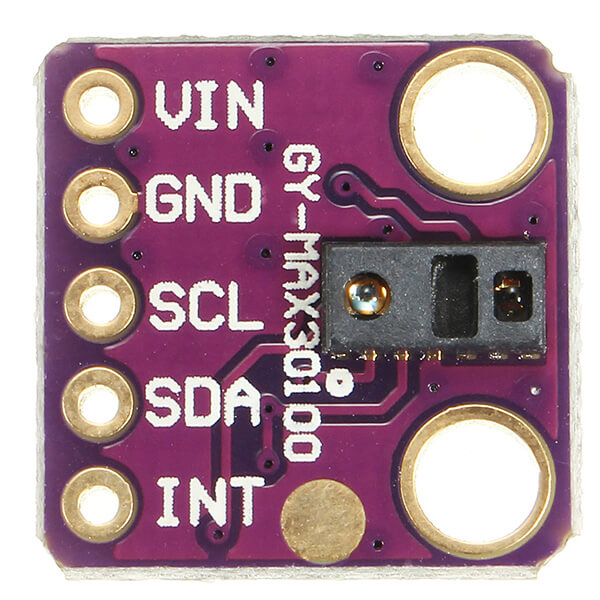
| 5 | Pulse Oximeter Sensor | MAX30100/MAX30102 I2C Pulse Oximeter Sensor | 1 | https://amzn.to/3sjdrNc |
| 4 | Jumper Wires | Male to Male Jumper Wires | 8 | https://amzn.to/2JWSR44 |
| 5 | Breadboard | Solderless Breadboard MIni | 1 | https://amzn.to/3n33uRT |
MAX30100 Pulse Oximeter Sensor
DS18B20 Temperature Sensor
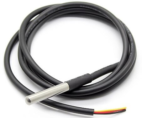
What is DS18B20 Temperature waterproof Sensor?
This is a pre-wired and waterproof version of the DS18B20 sensor. Useful when you need to measure something far away, or in wet conditions. The sensor can measure temperatures from -55 to 125°C (-67°F to +257°F). Actually, the cable of this sensor is jacketed in PVC.
DS18B20 is a digital sensor, hence there is no signal degradation over long distances. It is fairly precise, i.e ±0.5°C over much of the range. It provides up to 12 bits of precision from the onboard digital-to-analog converter. This sensor works great with any microcontroller using a single digital pin.
The downside is it uses the Dallas 1-Wire protocol, which is somewhat complex and requires a bunch of code to communicate.
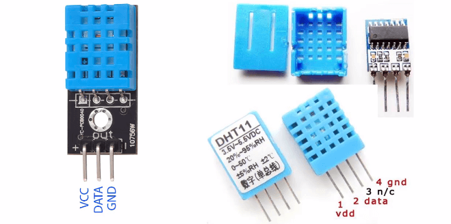
DHT11 Temperature & Humidity Sensor
What DHT11 Sensor?
The DHT11 is a simple, ultra-low-cost digital temperature & humidity sensor. DHT11 uses a capacitive humidity sensor and a thermistor to measure the surrounding temperature and humidity. It sends data in digital signal form so no analog input pin is required.
To grab data from DHT11 Sensor careful timing is required. It gets new data every 2 seconds. Hence, the readings of this sensor are always 2 seconds old.
To learn more about DHT11 Humidity/Temperature Sensor you can follow these posts:
- Interfacing DHT11 Humidity & Temperature Sensor with Arduino & LCD
- NodeMCU ESP8266 Monitoring DHT11/DHT22 Temperature and Humidity with Local Web Server
Circuit Diagram: Patient Health Monitoring System on ESP8266/ESP32
Now let us begin designing IoT Based Patient Health Monitoring with ESP8266/ESP32 Web Server. So the circuit diagram for interfacing MAX30100, DHT11 & DS18B20 with ESP8266 is given below.
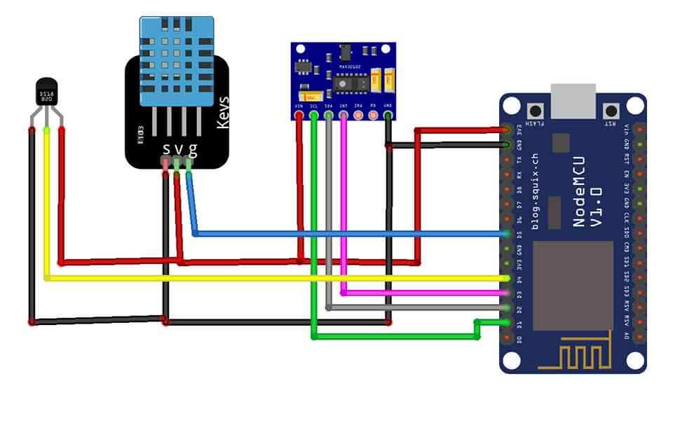
| MAX30100 Pins | NodeMCU ESP8266 Pins |
| SDA | D2 |
| SCL | D1 |
| INT | D3 |
| Vcc | 3.3V |
| GND | GND |
| DS18B20 Pins | NodeMCU ESP8266 Pins |
| Vcc | 3.3V |
| GND | GND |
| Signal | D4 |
| DHT11 Pins | NodeMCU ESP8266 PIns |
| Vcc | 3.3V |
| GND | GND |
| Signal | D5 |
Similarly, the circuit diagram for interfacing MAX30100, DHT11 & DS18B20 with ESP32 is provided below.
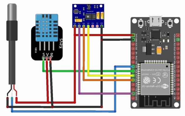
| MAX30100 Pins | ESP32 Pins |
| SDA | GPIO21 |
| SCL | GPIO22 |
| INT | GPIO19 |
| Vcc | 3.3V |
| GND | GND |
| DS18B20 Pins | ESP332 Pins |
| Vcc | 3.3V |
| GND | GND |
| Signal | GPIO5 |
| DHT11 Pins | ESP32 PIns |
| Vcc | 3.3V |
| GND | GND |
| Signal | GPIO18 |
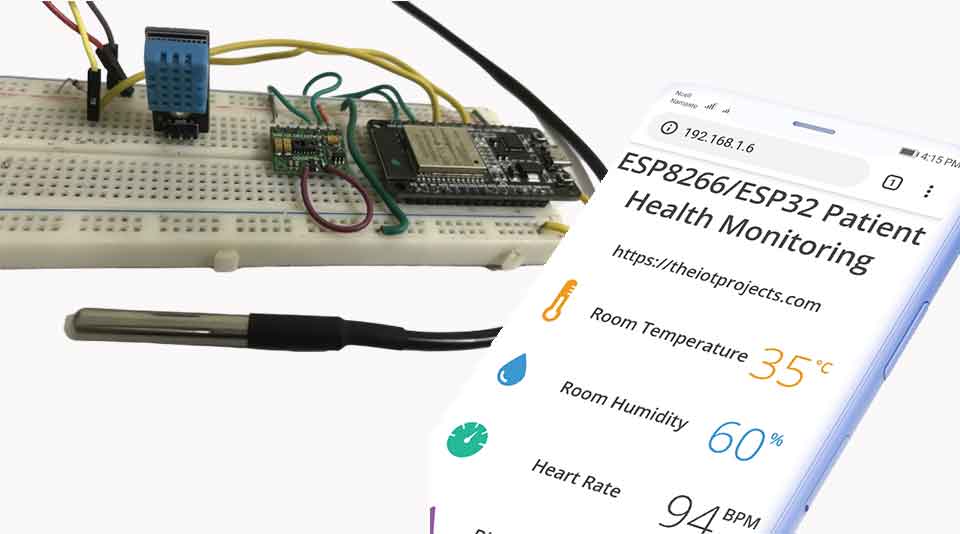
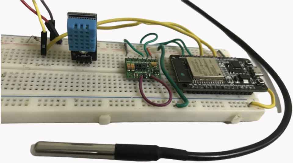
This is the circuit that I have assembled on a breadboard. This looks ugly and isn’t portable too. You can design custom PCBs for it.
Source Code/Program
The Program/Source Code for IoT Based Patient Health Monitoring System Using ESP8266/ESP32 Web Server is provided below. To run this program code in your Arduino IDE you need to install a few libraries. Download all the libraries mentioned below and add them to your Arduino IDE.
Patient Health Monitoring System Program Code for ESP8266
Before Uploading Code Make changes in the WiFi Network SSID & Password.
#include <ESP8266WebServer.h>
#include <Wire.h>
#include "MAX30100_PulseOximeter.h"
#include <OneWire.h>
#include <DallasTemperature.h>
//#include <dht.h>
#include "DHT.h"


#define DHTTYPE DHT11
const int DHTPin = D5;

#define DS18B20 D4
#define REPORTING_PERIOD_MS     1000

float temperature, humidity, BPM, SpO2, bodytemperature;

/*Put your SSID & Password*/
const char* ssid = "The IoT Projects";  // Enter SSID here
const char* password = "11122235122@kap";  //Enter Password here


DHT dht(DHTPin, DHTTYPE); //--> Initialize DHT sensor, DHT dht(Pin_used, Type_of_DHT_Sensor);
PulseOximeter pox;
uint32_t tsLastReport = 0;
OneWire oneWire(DS18B20);
DallasTemperature sensors(&oneWire);


ESP8266WebServer server(80);

void onBeatDetected()
{
  Serial.println("Beat!");
}

void setup() {
  Serial.begin(115200);
  pinMode(D5, OUTPUT);
  delay(100);

  Serial.println("Connecting to ");
  Serial.println(ssid);

  //connect to your local wi-fi network
  WiFi.begin(ssid, password);

  //check wi-fi is connected to wi-fi network
  while (WiFi.status() != WL_CONNECTED) {
    delay(1000);
    Serial.print(".");
  }
  Serial.println("");
  Serial.println("WiFi connected..!");
  Serial.print("Got IP: ");  Serial.println(WiFi.localIP());

  server.on("/", handle_OnConnect);
  server.onNotFound(handle_NotFound);

  server.begin();
  Serial.println("HTTP server started");

  Serial.print("Initializing pulse oximeter..");

  if (!pox.begin()) {
    Serial.println("FAILED");
    for (;;);
  } else {
    Serial.println("SUCCESS");
    pox.setOnBeatDetectedCallback(onBeatDetected);
  }

  pox.setIRLedCurrent(MAX30100_LED_CURR_7_6MA);

  // Register a callback for the beat detection

}
void loop() {
  server.handleClient();
  pox.update();
  sensors.requestTemperatures();
  float t = dht.readTemperature();
  String Temperature_Value = String(t);
  float h = dht.readHumidity();
  String Humidity_Value = String(h);
  temperature = t;
  humidity = h;
  BPM = pox.getHeartRate();
  SpO2 = pox.getSpO2();
  bodytemperature = sensors.getTempCByIndex(0);


  if (millis() - tsLastReport > REPORTING_PERIOD_MS)
  {
    Serial.print("Room Temperature: ");
    Serial.print(t);
    Serial.println("°C");

    Serial.print("Room Humidity: ");
    Serial.print(h);
    Serial.println("%");

    Serial.print("BPM: ");
    Serial.println(BPM);

    Serial.print("SpO2: ");
    Serial.print(SpO2);
    Serial.println("%");

    Serial.print("Body Temperature: ");
    Serial.print(bodytemperature);
    Serial.println("°C");

    Serial.println("*********************************");
    Serial.println();

    tsLastReport = millis();
  }

}

void handle_OnConnect() {

  server.send(200, "text/html", SendHTML(temperature, humidity, BPM, SpO2, bodytemperature));
}

void handle_NotFound() {
  server.send(404, "text/plain", "Not found");
}

String SendHTML(float temperature, float humidity, float BPM, float SpO2, float bodytemperature) {
  String ptr = "<!DOCTYPE html>";
  ptr += "<html>";
  ptr += "<head>";
  ptr += "<title>ESP Patient Health Monitoring</title>";
  ptr += "<meta name='viewport' content='width=device-width, initial-scale=1.0'>";
  ptr += "<link href='https://fonts.googleapis.com/css?family=Open+Sans:300,400,600' rel='stylesheet'>";
  ptr += "<style>";
  ptr += "html { font-family: 'Open Sans', sans-serif; display: block; margin: 0px auto; text-align: center;color: #444444;}";
  ptr += "body{margin: 0px;} ";
  ptr += "h1 {margin: 50px auto 30px;} ";
  ptr += ".side-by-side{display: table-cell;vertical-align: middle;position: relative;}";
  ptr += ".text{font-weight: 600;font-size: 19px;width: 200px;}";
  ptr += ".reading{font-weight: 300;font-size: 50px;padding-right: 25px;}";
  ptr += ".temperature .reading{color: #F29C1F;}";
  ptr += ".humidity .reading{color: #3B97D3;}";
  ptr += ".BPM .reading{color: #FF0000;}";
  ptr += ".SpO2 .reading{color: #955BA5;}";
  ptr += ".bodytemperature .reading{color: #F29C1F;}";
  ptr += ".superscript{font-size: 17px;font-weight: 600;position: absolute;top: 10px;}";
  ptr += ".data{padding: 10px;}";
  ptr += ".container{display: table;margin: 0 auto;}";
  ptr += ".icon{width:65px}";
  ptr += "</style>";
  ptr += "</head>";
  ptr += "<body>";
  ptr += "<h1>ESP8266/ESP32 Patient Health Monitoring</h1>";
  ptr += "<h3>https://theiotprojects.com</a></h3>";
  ptr += "<div class='container'>";

  ptr += "<div class='data temperature'>";
  ptr += "<div class='side-by-side icon'>";
  ptr += "<svg enable-background='new 0 0 19.438 54.003'height=54.003px id=Layer_1 version=1.1 viewBox='0 0 19.438 54.003'width=19.438px x=0px xml:space=preserve xmlns=http://www.w3.org/2000/svg xmlns:xlink=http://www.w3.org/1999/xlink y=0px><g><path d='M11.976,8.82v-2h4.084V6.063C16.06,2.715,13.345,0,9.996,0H9.313C5.965,0,3.252,2.715,3.252,6.063v30.982";
  ptr += "C1.261,38.825,0,41.403,0,44.286c0,5.367,4.351,9.718,9.719,9.718c5.368,0,9.719-4.351,9.719-9.718";
  ptr += "c0-2.943-1.312-5.574-3.378-7.355V18.436h-3.914v-2h3.914v-2.808h-4.084v-2h4.084V8.82H11.976z M15.302,44.833";
  ptr += "c0,3.083-2.5,5.583-5.583,5.583s-5.583-2.5-5.583-5.583c0-2.279,1.368-4.236,3.326-5.104V24.257C7.462,23.01,8.472,22,9.719,22";
  ptr += "s2.257,1.01,2.257,2.257V39.73C13.934,40.597,15.302,42.554,15.302,44.833z'fill=#F29C21 /></g></svg>";
  ptr += "</div>";
  ptr += "<div class='side-by-side text'>Room Temperature</div>";
  ptr += "<div class='side-by-side reading'>";
  //ptr += (int)temperature;
  ptr += (int)35;
  ptr += "<span class='superscript'>°C</span></div>";
  ptr += "</div>";

  ptr += "<div class='data humidity'>";
  ptr += "<div class='side-by-side icon'>";
  ptr += "<svg enable-background='new 0 0 29.235 40.64'height=40.64px id=Layer_1 version=1.1 viewBox='0 0 29.235 40.64'width=29.235px x=0px xml:space=preserve xmlns=http://www.w3.org/2000/svg xmlns:xlink=http://www.w3.org/1999/xlink y=0px><path d='M14.618,0C14.618,0,0,17.95,0,26.022C0,34.096,6.544,40.64,14.618,40.64s14.617-6.544,14.617-14.617";
  ptr += "C29.235,17.95,14.618,0,14.618,0z M13.667,37.135c-5.604,0-10.162-4.56-10.162-10.162c0-0.787,0.638-1.426,1.426-1.426";
  ptr += "c0.787,0,1.425,0.639,1.425,1.426c0,4.031,3.28,7.312,7.311,7.312c0.787,0,1.425,0.638,1.425,1.425";
  ptr += "C15.093,36.497,14.455,37.135,13.667,37.135z'fill=#3C97D3 /></svg>";
  ptr += "</div>";
  ptr += "<div class='side-by-side text'>Room Humidity</div>";
  ptr += "<div class='side-by-side reading'>";
  //ptr += (int)humidity;
  ptr += (int)60;
  ptr += "<span class='superscript'>%</span></div>";
  ptr += "</div>";

  ptr += "<div class='data Heart Rate'>";
  ptr += "<div class='side-by-side icon'>";
  ptr += "<svg enable-background='new 0 0 40.542 40.541'height=40.541px id=Layer_1 version=1.1 viewBox='0 0 40.542 40.541'width=40.542px x=0px xml:space=preserve xmlns=http://www.w3.org/2000/svg xmlns:xlink=http://www.w3.org/1999/xlink y=0px><g><path d='M34.313,20.271c0-0.552,0.447-1,1-1h5.178c-0.236-4.841-2.163-9.228-5.214-12.593l-3.425,3.424";
  ptr += "c-0.195,0.195-0.451,0.293-0.707,0.293s-0.512-0.098-0.707-0.293c-0.391-0.391-0.391-1.023,0-1.414l3.425-3.424";
  ptr += "c-3.375-3.059-7.776-4.987-12.634-5.215c0.015,0.067,0.041,0.13,0.041,0.202v4.687c0,0.552-0.447,1-1,1s-1-0.448-1-1V0.25";
  ptr += "c0-0.071,0.026-0.134,0.041-0.202C14.39,0.279,9.936,2.256,6.544,5.385l3.576,3.577c0.391,0.391,0.391,1.024,0,1.414";
  ptr += "c-0.195,0.195-0.451,0.293-0.707,0.293s-0.512-0.098-0.707-0.293L5.142,6.812c-2.98,3.348-4.858,7.682-5.092,12.459h4.804";
  ptr += "c0.552,0,1,0.448,1,1s-0.448,1-1,1H0.05c0.525,10.728,9.362,19.271,20.22,19.271c10.857,0,19.696-8.543,20.22-19.271h-5.178";
  ptr += "C34.76,21.271,34.313,20.823,34.313,20.271z M23.084,22.037c-0.559,1.561-2.274,2.372-3.833,1.814";
  ptr += "c-1.561-0.557-2.373-2.272-1.815-3.833c0.372-1.041,1.263-1.737,2.277-1.928L25.2,7.202L22.497,19.05";
  ptr += "C23.196,19.843,23.464,20.973,23.084,22.037z'fill=#26B999 /></g></svg>";
  ptr += "</div>";
  ptr += "<div class='side-by-side text'>Heart Rate</div>";
  ptr += "<div class='side-by-side reading'>";
  ptr += (int)BPM;
  ptr += "<span class='superscript'>BPM</span></div>";
  ptr += "</div>";

  ptr += "<div class='data Blood Oxygen'>";
  ptr += "<div class='side-by-side icon'>";
  ptr += "<svg enable-background='new 0 0 58.422 40.639'height=40.639px id=Layer_1 version=1.1 viewBox='0 0 58.422 40.639'width=58.422px x=0px xml:space=preserve xmlns=http://www.w3.org/2000/svg xmlns:xlink=http://www.w3.org/1999/xlink y=0px><g><path d='M58.203,37.754l0.007-0.004L42.09,9.935l-0.001,0.001c-0.356-0.543-0.969-0.902-1.667-0.902";
  ptr += "c-0.655,0-1.231,0.32-1.595,0.808l-0.011-0.007l-0.039,0.067c-0.021,0.03-0.035,0.063-0.054,0.094L22.78,37.692l0.008,0.004";
  ptr += "c-0.149,0.28-0.242,0.594-0.242,0.934c0,1.102,0.894,1.995,1.994,1.995v0.015h31.888c1.101,0,1.994-0.893,1.994-1.994";
  ptr += "C58.422,38.323,58.339,38.024,58.203,37.754z'fill=#955BA5 /><path d='M19.704,38.674l-0.013-0.004l13.544-23.522L25.13,1.156l-0.002,0.001C24.671,0.459,23.885,0,22.985,0";
  ptr += "c-0.84,0-1.582,0.41-2.051,1.038l-0.016-0.01L20.87,1.114c-0.025,0.039-0.046,0.082-0.068,0.124L0.299,36.851l0.013,0.004";
  ptr += "C0.117,37.215,0,37.62,0,38.059c0,1.412,1.147,2.565,2.565,2.565v0.015h16.989c-0.091-0.256-0.149-0.526-0.149-0.813";
  ptr += "C19.405,39.407,19.518,39.019,19.704,38.674z'fill=#955BA5 /></g></svg>";
  ptr += "</div>";
  ptr += "<div class='side-by-side text'>Blood Oxygen</div>";
  ptr += "<div class='side-by-side reading'>";
  ptr += (int)SpO2;
  ptr += "<span class='superscript'>%</span></div>";
  ptr += "</div>";

  ptr += "<div class='data Body Temperature'>";
  ptr += "<div class='side-by-side icon'>";
  ptr += "<svg enable-background='new 0 0 19.438 54.003'height=54.003px id=Layer_1 version=1.1 viewBox='0 0 19.438 54.003'width=19.438px x=0px xml:space=preserve xmlns=http://www.w3.org/2000/svg xmlns:xlink=http://www.w3.org/1999/xlink y=0px><g><path d='M11.976,8.82v-2h4.084V6.063C16.06,2.715,13.345,0,9.996,0H9.313C5.965,0,3.252,2.715,3.252,6.063v30.982";
  ptr += "C1.261,38.825,0,41.403,0,44.286c0,5.367,4.351,9.718,9.719,9.718c5.368,0,9.719-4.351,9.719-9.718";
  ptr += "c0-2.943-1.312-5.574-3.378-7.355V18.436h-3.914v-2h3.914v-2.808h-4.084v-2h4.084V8.82H11.976z M15.302,44.833";
  ptr += "c0,3.083-2.5,5.583-5.583,5.583s-5.583-2.5-5.583-5.583c0-2.279,1.368-4.236,3.326-5.104V24.257C7.462,23.01,8.472,22,9.719,22";
  ptr += "s2.257,1.01,2.257,2.257V39.73C13.934,40.597,15.302,42.554,15.302,44.833z'fill=#F29C21 /></g></svg>";
  ptr += "</div>";
  ptr += "<div class='side-by-side text'>Body Temperature</div>";
  ptr += "<div class='side-by-side reading'>";
  ptr += (int)bodytemperature;
  ptr += "<span class='superscript'>°C</span></div>";
  ptr += "</div>";

  ptr += "</div>";
  ptr += "</body>";
  ptr += "</html>";
  return ptr;
}
Patient Health Monitoring System Program Code for ESP32
Before Uploading Code Make changes in the WiFi Network SSID & Password.
#include <WiFi.h>
#include <WebServer.h>
#include <Wire.h>
#include "MAX30100_PulseOximeter.h"
#include <OneWire.h>
#include <DallasTemperature.h>
#include <dht.h>

#define DHT11_PIN 18
#define DS18B20 5
#define REPORTING_PERIOD_MS     1000

float temperature, humidity, BPM, SpO2, bodytemperature;

/*Put your SSID & Password*/
const char* ssid = "The IoT Projects";  // Enter SSID here
const char* password = "11122235122@kap";  //Enter Password here

dht DHT;
PulseOximeter pox;
uint32_t tsLastReport = 0;
OneWire oneWire(DS18B20);
DallasTemperature sensors(&oneWire);


WebServer server(80);

void onBeatDetected()
{
  Serial.println("Beat!");
}

void setup() {
  Serial.begin(115200);
  pinMode(19, OUTPUT);
  delay(100);

  Serial.println("Connecting to ");
  Serial.println(ssid);

  //connect to your local wi-fi network
  WiFi.begin(ssid, password);

  //check wi-fi is connected to wi-fi network
  while (WiFi.status() != WL_CONNECTED) {
  delay(1000);
  Serial.print(".");
  }
  Serial.println("");
  Serial.println("WiFi connected..!");
  Serial.print("Got IP: ");  Serial.println(WiFi.localIP());

  server.on("/", handle_OnConnect);
  server.onNotFound(handle_NotFound);

  server.begin();
  Serial.println("HTTP server started");

  Serial.print("Initializing pulse oximeter..");

  if (!pox.begin()) {
    Serial.println("FAILED");
    for (;;);
  } else {
    Serial.println("SUCCESS");
    pox.setOnBeatDetectedCallback(onBeatDetected);
  }

   pox.setIRLedCurrent(MAX30100_LED_CURR_7_6MA);

  // Register a callback for the beat detection

}
void loop() {
  server.handleClient();
  pox.update();
  sensors.requestTemperatures();
  int chk = DHT.read11(DHT11_PIN);

  temperature = DHT.temperature;
  humidity = DHT.humidity;
  BPM = pox.getHeartRate();
  SpO2 = pox.getSpO2();
  bodytemperature = sensors.getTempCByIndex(0);


  if (millis() - tsLastReport > REPORTING_PERIOD_MS)
  {
    Serial.print("Room Temperature: ");
    Serial.print(DHT.temperature);
    Serial.println("°C");

    Serial.print("Room Humidity: ");
    Serial.print(DHT.humidity);
    Serial.println("%");

    Serial.print("BPM: ");
    Serial.println(BPM);

    Serial.print("SpO2: ");
    Serial.print(SpO2);
    Serial.println("%");

    Serial.print("Body Temperature: ");
    Serial.print(bodytemperature);
    Serial.println("°C");

    Serial.println("*********************************");
    Serial.println();

    tsLastReport = millis();
  }

}

void handle_OnConnect() {

  server.send(200, "text/html", SendHTML(temperature, humidity, BPM, SpO2, bodytemperature));
}

void handle_NotFound(){
  server.send(404, "text/plain", "Not found");
}

  String SendHTML(float temperature,float humidity,float BPM,float SpO2, float bodytemperature){
  String ptr = "<!DOCTYPE html>";
  ptr +="<html>";
  ptr +="<head>";
  ptr +="<title>ESP Patient Health Monitoring</title>";
  ptr +="<meta name='viewport' content='width=device-width, initial-scale=1.0'>";
  ptr +="<link href='https://fonts.googleapis.com/css?family=Open+Sans:300,400,600' rel='stylesheet'>";
  ptr +="<style>";
  ptr +="html { font-family: 'Open Sans', sans-serif; display: block; margin: 0px auto; text-align: center;color: #444444;}";
  ptr +="body{margin: 0px;} ";
  ptr +="h1 {margin: 50px auto 30px;} ";
  ptr +=".side-by-side{display: table-cell;vertical-align: middle;position: relative;}";
  ptr +=".text{font-weight: 600;font-size: 19px;width: 200px;}";
  ptr +=".reading{font-weight: 300;font-size: 50px;padding-right: 25px;}";
  ptr +=".temperature .reading{color: #F29C1F;}";
  ptr +=".humidity .reading{color: #3B97D3;}";
  ptr +=".BPM .reading{color: #FF0000;}";
  ptr +=".SpO2 .reading{color: #955BA5;}";
  ptr +=".bodytemperature .reading{color: #F29C1F;}";
  ptr +=".superscript{font-size: 17px;font-weight: 600;position: absolute;top: 10px;}";
  ptr +=".data{padding: 10px;}";
  ptr +=".container{display: table;margin: 0 auto;}";
  ptr +=".icon{width:65px}";
  ptr +="</style>";
  ptr +="</head>";
  ptr +="<body>";
  ptr +="<h1>ESP8266/ESP32 Patient Health Monitoring</h1>";
  ptr +="<h3>https://theiotprojects.com</h3>";
  ptr +="<div class='container'>";

  ptr +="<div class='data temperature'>";
  ptr +="<div class='side-by-side icon'>";
  ptr +="<svg enable-background='new 0 0 19.438 54.003'height=54.003px id=Layer_1 version=1.1 viewBox='0 0 19.438 54.003'width=19.438px x=0px xml:space=preserve xmlns=http://www.w3.org/2000/svg xmlns:xlink=http://www.w3.org/1999/xlink y=0px><g><path d='M11.976,8.82v-2h4.084V6.063C16.06,2.715,13.345,0,9.996,0H9.313C5.965,0,3.252,2.715,3.252,6.063v30.982";
  ptr +="C1.261,38.825,0,41.403,0,44.286c0,5.367,4.351,9.718,9.719,9.718c5.368,0,9.719-4.351,9.719-9.718";
  ptr +="c0-2.943-1.312-5.574-3.378-7.355V18.436h-3.914v-2h3.914v-2.808h-4.084v-2h4.084V8.82H11.976z M15.302,44.833";
  ptr +="c0,3.083-2.5,5.583-5.583,5.583s-5.583-2.5-5.583-5.583c0-2.279,1.368-4.236,3.326-5.104V24.257C7.462,23.01,8.472,22,9.719,22";
  ptr +="s2.257,1.01,2.257,2.257V39.73C13.934,40.597,15.302,42.554,15.302,44.833z'fill=#F29C21 /></g></svg>";
  ptr +="</div>";
  ptr +="<div class='side-by-side text'>Room Temperature</div>";
  ptr +="<div class='side-by-side reading'>";
  ptr +=(int)temperature;
  ptr +="<span class='superscript'>°C</span></div>";
  ptr +="</div>";

  ptr +="<div class='data humidity'>";
  ptr +="<div class='side-by-side icon'>";
  ptr +="<svg enable-background='new 0 0 29.235 40.64'height=40.64px id=Layer_1 version=1.1 viewBox='0 0 29.235 40.64'width=29.235px x=0px xml:space=preserve xmlns=http://www.w3.org/2000/svg xmlns:xlink=http://www.w3.org/1999/xlink y=0px><path d='M14.618,0C14.618,0,0,17.95,0,26.022C0,34.096,6.544,40.64,14.618,40.64s14.617-6.544,14.617-14.617";
  ptr +="C29.235,17.95,14.618,0,14.618,0z M13.667,37.135c-5.604,0-10.162-4.56-10.162-10.162c0-0.787,0.638-1.426,1.426-1.426";
  ptr +="c0.787,0,1.425,0.639,1.425,1.426c0,4.031,3.28,7.312,7.311,7.312c0.787,0,1.425,0.638,1.425,1.425";
  ptr +="C15.093,36.497,14.455,37.135,13.667,37.135z'fill=#3C97D3 /></svg>";
  ptr +="</div>";
  ptr +="<div class='side-by-side text'>Room Humidity</div>";
  ptr +="<div class='side-by-side reading'>";
  ptr +=(int)humidity;
  ptr +="<span class='superscript'>%</span></div>";
  ptr +="</div>";

  ptr +="<div class='data Heart Rate'>";
  ptr +="<div class='side-by-side icon'>";
  ptr +="<svg enable-background='new 0 0 40.542 40.541'height=40.541px id=Layer_1 version=1.1 viewBox='0 0 40.542 40.541'width=40.542px x=0px xml:space=preserve xmlns=http://www.w3.org/2000/svg xmlns:xlink=http://www.w3.org/1999/xlink y=0px><g><path d='M34.313,20.271c0-0.552,0.447-1,1-1h5.178c-0.236-4.841-2.163-9.228-5.214-12.593l-3.425,3.424";
  ptr +="c-0.195,0.195-0.451,0.293-0.707,0.293s-0.512-0.098-0.707-0.293c-0.391-0.391-0.391-1.023,0-1.414l3.425-3.424";
  ptr +="c-3.375-3.059-7.776-4.987-12.634-5.215c0.015,0.067,0.041,0.13,0.041,0.202v4.687c0,0.552-0.447,1-1,1s-1-0.448-1-1V0.25";
  ptr +="c0-0.071,0.026-0.134,0.041-0.202C14.39,0.279,9.936,2.256,6.544,5.385l3.576,3.577c0.391,0.391,0.391,1.024,0,1.414";
  ptr +="c-0.195,0.195-0.451,0.293-0.707,0.293s-0.512-0.098-0.707-0.293L5.142,6.812c-2.98,3.348-4.858,7.682-5.092,12.459h4.804";
  ptr +="c0.552,0,1,0.448,1,1s-0.448,1-1,1H0.05c0.525,10.728,9.362,19.271,20.22,19.271c10.857,0,19.696-8.543,20.22-19.271h-5.178";
  ptr +="C34.76,21.271,34.313,20.823,34.313,20.271z M23.084,22.037c-0.559,1.561-2.274,2.372-3.833,1.814";
  ptr +="c-1.561-0.557-2.373-2.272-1.815-3.833c0.372-1.041,1.263-1.737,2.277-1.928L25.2,7.202L22.497,19.05";
  ptr +="C23.196,19.843,23.464,20.973,23.084,22.037z'fill=#26B999 /></g></svg>";
  ptr +="</div>";
  ptr +="<div class='side-by-side text'>Heart Rate</div>";
  ptr +="<div class='side-by-side reading'>";
  ptr +=(int)BPM;
  ptr +="<span class='superscript'>BPM</span></div>";
  ptr +="</div>";

  ptr +="<div class='data Blood Oxygen'>";
  ptr +="<div class='side-by-side icon'>";
  ptr +="<svg enable-background='new 0 0 58.422 40.639'height=40.639px id=Layer_1 version=1.1 viewBox='0 0 58.422 40.639'width=58.422px x=0px xml:space=preserve xmlns=http://www.w3.org/2000/svg xmlns:xlink=http://www.w3.org/1999/xlink y=0px><g><path d='M58.203,37.754l0.007-0.004L42.09,9.935l-0.001,0.001c-0.356-0.543-0.969-0.902-1.667-0.902";
  ptr +="c-0.655,0-1.231,0.32-1.595,0.808l-0.011-0.007l-0.039,0.067c-0.021,0.03-0.035,0.063-0.054,0.094L22.78,37.692l0.008,0.004";
  ptr +="c-0.149,0.28-0.242,0.594-0.242,0.934c0,1.102,0.894,1.995,1.994,1.995v0.015h31.888c1.101,0,1.994-0.893,1.994-1.994";
  ptr +="C58.422,38.323,58.339,38.024,58.203,37.754z'fill=#955BA5 /><path d='M19.704,38.674l-0.013-0.004l13.544-23.522L25.13,1.156l-0.002,0.001C24.671,0.459,23.885,0,22.985,0";
  ptr +="c-0.84,0-1.582,0.41-2.051,1.038l-0.016-0.01L20.87,1.114c-0.025,0.039-0.046,0.082-0.068,0.124L0.299,36.851l0.013,0.004";
  ptr +="C0.117,37.215,0,37.62,0,38.059c0,1.412,1.147,2.565,2.565,2.565v0.015h16.989c-0.091-0.256-0.149-0.526-0.149-0.813";
  ptr +="C19.405,39.407,19.518,39.019,19.704,38.674z'fill=#955BA5 /></g></svg>";
  ptr +="</div>";
  ptr +="<div class='side-by-side text'>Blood Oxygen</div>";
  ptr +="<div class='side-by-side reading'>";
  ptr +=(int)SpO2;
  ptr +="<span class='superscript'>%</span></div>";
  ptr +="</div>";

  ptr +="<div class='data Body Temperature'>";
  ptr +="<div class='side-by-side icon'>";
  ptr +="<svg enable-background='new 0 0 19.438 54.003'height=54.003px id=Layer_1 version=1.1 viewBox='0 0 19.438 54.003'width=19.438px x=0px xml:space=preserve xmlns=http://www.w3.org/2000/svg xmlns:xlink=http://www.w3.org/1999/xlink y=0px><g><path d='M11.976,8.82v-2h4.084V6.063C16.06,2.715,13.345,0,9.996,0H9.313C5.965,0,3.252,2.715,3.252,6.063v30.982";
  ptr +="C1.261,38.825,0,41.403,0,44.286c0,5.367,4.351,9.718,9.719,9.718c5.368,0,9.719-4.351,9.719-9.718";
  ptr +="c0-2.943-1.312-5.574-3.378-7.355V18.436h-3.914v-2h3.914v-2.808h-4.084v-2h4.084V8.82H11.976z M15.302,44.833";
  ptr +="c0,3.083-2.5,5.583-5.583,5.583s-5.583-2.5-5.583-5.583c0-2.279,1.368-4.236,3.326-5.104V24.257C7.462,23.01,8.472,22,9.719,22";
  ptr +="s2.257,1.01,2.257,2.257V39.73C13.934,40.597,15.302,42.554,15.302,44.833z'fill=#F29C21 /></g></svg>";
  ptr +="</div>";
  ptr +="<div class='side-by-side text'>Body Temperature</div>";
  ptr +="<div class='side-by-side reading'>";
  ptr +=(int)bodytemperature;
  ptr +="<span class='superscript'>°C</span></div>";
  ptr +="</div>";

  ptr +="</div>";
  ptr +="</body>";
  ptr +="</html>";
  return ptr;
}
Project Demonstration
Once the code is uploaded to your respective board, you can open the serial monitor to see the program into action. The NodeMCU ESP8266/ESP32 will try to connect to your WiFi Network. Once connected, it will display the ESP IP Address.
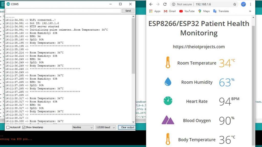
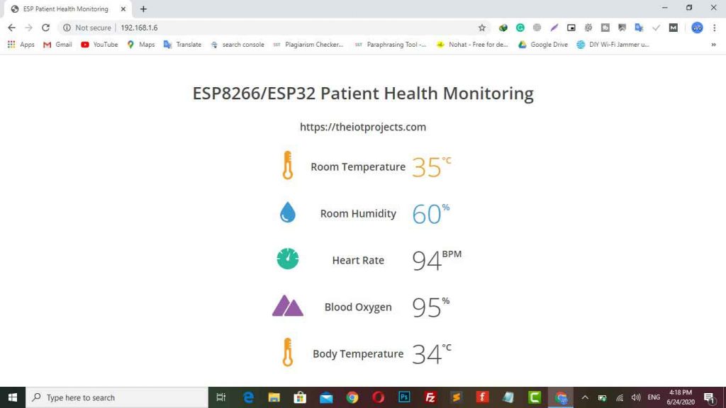
Now, copy the ESP8266/ESP32 IP Address and paste on Web Browser. It will display you the room temperature, room humidity, Heart Rate, Blood Oxygen Level, and Body Temperature, etc. as shown in the below images.
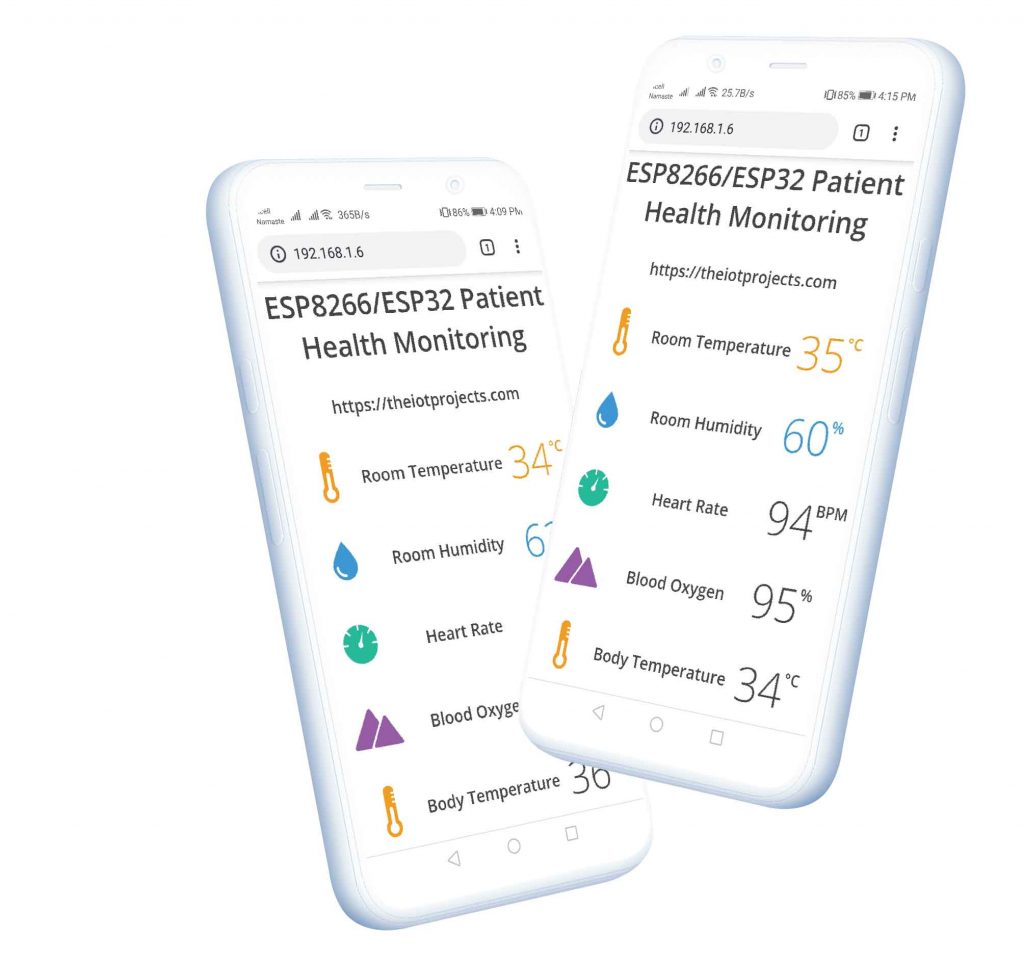
Similarly, you can monitor your patient’s health from any device that features a browser. The below image is the view of the Patient Health Status on Android SmartPhone. Simply copy the ESP IP Address and paste on the browser of any device.
Conclusion
In this tutorial, we have shown you how to make IoT Based Patient Health Monitoring System Using ESP8266/ESP32 Web Server. I hope this tutorial was interesting to you. If you need any type of help related to this project then do let me know in the comment section below.
Our Previous Post:
- BME280 Based Mini Weather Station using ESP8266/ESP32
- Insert Data into MySQL Database with ESP8266 Development Board
- Flood Monitoring System Using NodeMCU & Thingspeak
- IoT based Silent Intruder Alarm using Arduino
- IoT Based Voice Controlled Home Automation Using NodeMCU & Android
- RFID Based Attendance System Using NodeMCU with PHP Web App
- IoT Based RFID Smart Door Lock System Using NodeMCU ESp8266
- Home Automation with MIT App Inventor and ESP8266
- ESP8266 Plot Sensor readings to Webserver in Real-Time Chart
- IoT Based RFID Attendance System using ESP32


It does not working.. The MAX30100 is showing the values as 0 although the Temperature value is coming.. Please give a resolution
Check Connection sometimes loose connection create a problem like this
i have some problem … the max30100 not masaring .. led is on but not masaring bpm.00% and spo0.0% .. all the connections is ok ..
Solder max30100 pins it always create problems like this due to loose connections. Mine problem was solved after soldering.
Hello how are you, I would like to know how I can remove the server from esp and host it on an online server could you give me a route to start investigating
i use another code from examples and the max 30100 is good and worked well .. but when use the project code in thes page is remain bpm0.0% spo 0.0% .. please help me on thes project
Bro please send the code that max30100 works
what are other tools u used
In file included from C:\Users\HP\Documents\Arduino\libraries\DHT_sensor_library\dht.h:18:0,
from C:\Users\HP\Documents\Arduino\libraries\DHT_sensor_library\dht.cpp:30:
C:\Users\HP\Documents\Arduino\libraries\DHT_sensor_library\dht.cpp: In member function ‘int dht::_readSensor(uint8_t, uint8_t)’:
C:\Users\HP\AppData\Local\Arduino15\packages\esp32\hardware\esp32\1.0.4\cores\esp32/Arduino.h:106:91: error: cannot convert ‘volatile uint32_t* {aka volatile unsigned int*}’ to ‘volatile uint8_t* {aka volatile unsigned char*}’ in initialization
#define portInputRegister(port) ((volatile uint32_t*)((port)?GPIO_IN1_REG:GPIO_IN_REG))
^
C:\Users\HP\Documents\Arduino\libraries\DHT_sensor_library\dht.cpp:116:29: note: in expansion of macro ‘portInputRegister’
volatile uint8_t *PIR = portInputRegister(port);
^
Multiple libraries were found for “WiFi.h”
Used: C:\Users\HP\AppData\Local\Arduino15\packages\esp32\hardware\esp32\1.0.4\libraries\WiFi
Not used: C:\Program Files (x86)\Arduino\libraries\WiFi
exit status 1
Error compiling for board ESP32 Dev Module.
problum only with max30100, the small IC 6pins getting very hot, its not working……. pls help
please i want to know if the readings can be accessed anywhere with internet connections or is it just ordinary wifi connection? also, i will be glad if you can help me ot with esp32 and esp8266 proteus library
hello;i am also getting the same error…can u please help me if u have rectified your error
Please how did you calibrate your body temperature sensor
hello i am heavibg an erorr “DHT does not name a type”, please can you help
Install All the required library first.
i did that but on the serial monitor the oximeter is showing 0 value for pulse and S02. it is not changing value. only humidity, bodytemperature and roomtemperature is working.
Please,I have the same problem. When I use only max30100 it works,after I use both ds18b20 and max30100,the values for max30100 are 0. Can you help me please? It’s important to fix it as soon as possible 🙁 I realised that when I use only an example,not with espwifi library,they both work perfectly. When I puts the code for web server,only temperatur values are good.
bro i am trying to apply ur project work
do u have any report
the display on my serial monitor does not come out, do you have a solution?
Bro plz also add lcd display to it so we can see output in both in device and lcd screen plz… .
can i know u find the problem and solve it ady?
Bro can you make video from combining componen in circuit diagram, connecting to webserver, and result IoT
Can u provide me a readymade health monitoring system using nodeMcu? I will pay for it