Overcurrent Protection Circuit using Arduino & CT Sensor
Arduino Based AC Overcurrent Protection Circuit
Overview
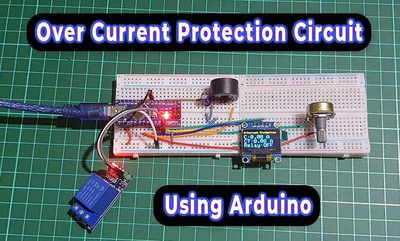
In this tutorial, I will guide you through the process of building a highly effective Overcurrent Protection Circuit using Arduino & CT Sensor. Our main components for this project will include an Arduino microcontroller and a ZMCT103C current sensor. With a 5V DC single-channel relay, we will have the ability to manage various household appliances connected to this circuit. To enhance the usability of this project for everyday use, we will also add a small 0.96-inch OLED display. This display will provide real-time information such as current sensor readings, current threshold values, and the status of the relay (whether it’s ON or OFF).
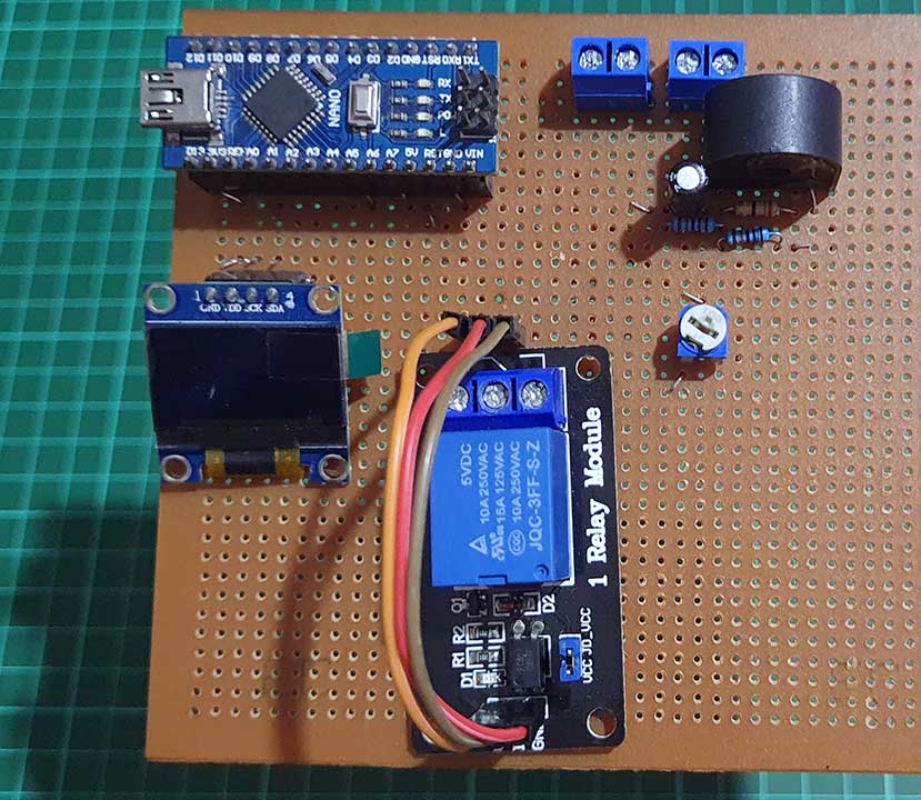
We will also include a 10k potentiometer in the circuit for adjusting the threshold value to our specific requirements. This project not only ensures the safety of your appliances but also provides a user-friendly interface for monitoring and controlling the current flow. So, let’s dive in and start building this overcurrent protection circuit!
Components Required
Following is the list of the components that are required for making an Overcurrent Protection Circuit using Arduino & CT Sensor. You can easily purchase them from Amazon and Aliexpress.
| S.N | COMPONENTS NAME | QUANTITY | PURCHASE LINKS |
|---|---|---|---|
| 1 | Arduino Nano | 1 | Amazon | AliExpress |
| 2 | ZMCT103C Current Sensor | 1 | Amazon | AliExpress |
| 3 | 33-ohm resistor | 1 | Amazon | AliExpress |
| 4 | 100k ohm resistor | 2 | Amazon | AliExpress |
| 5 | 10uf capacitor | 1 | Amazon | AliExpress |
| 6 | 0.96 inch OLED Display | 1 | Amazon | AliExpress |
| 7 | Single Channel Relay Module | 1 | Amazon | AliExpress |
| 8 | Jumper wires | 10 | Amazon | AliExpress |
| 9 | Breadboard | 1 | Amazon | AliExpress |
ZMCT103C CT Sensor
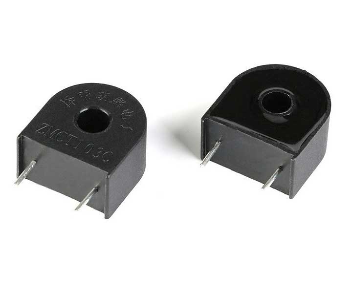
The ZMCT103C current sensor is a high-precision micro current transformer that can be used to measure AC mains current up to 5 Amps. It has a turns ratio of 1000:1, which means that a 5 Amp current through the primary will produce a 5mA current in the secondary. This small current can be easily read by an Arduino. In our previous project, we have already discussed the ZMCT103C sensor and how to measure current across it with an Arduino microcontroller.
Circuit Diagram
Let’s get started by gathering all the components and assembling them by following the circuit diagram.
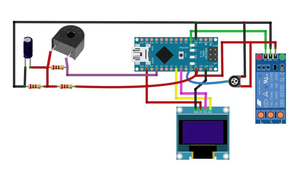
The circuit connections are pretty straightforward.
Interfacing ZMCT103C CT sensor with Arduino
First, let’s set up the ZMCT103C sensor with the Arduino. We’ll create a simple voltage divider circuit using some components:
- Use R6 as a burden resistor.
- Connect R8 and R7 as a potential divider.
- Add C3 as a smoothing capacitor.
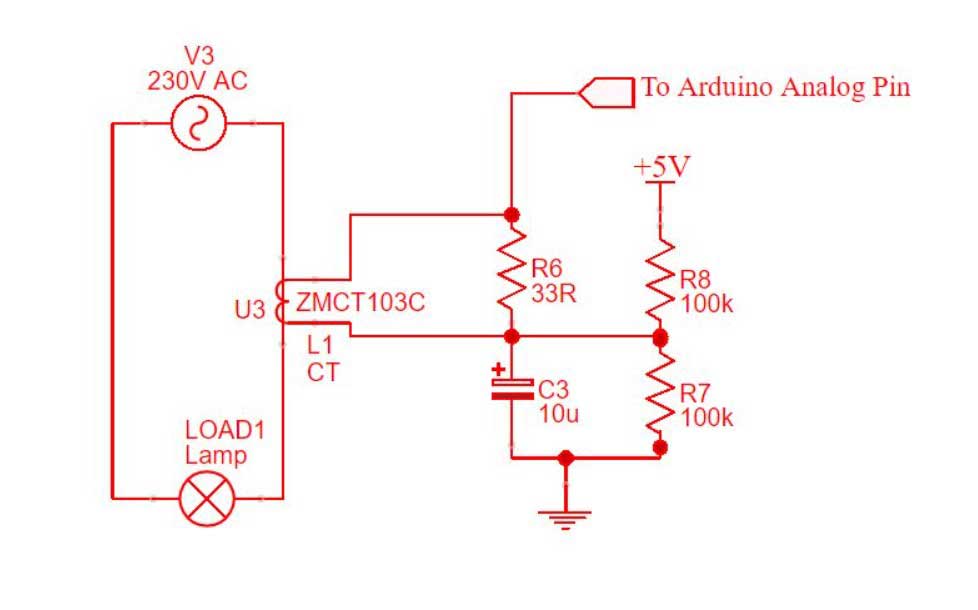
Here’s the idea: When 5 amps of current pass through the primary winding of the sensor, 5 milliamps flow through the secondary winding (this is determined by the transformation ratio). This secondary current creates a voltage drop of 165 mV, which we calculate using Ohm’s law (V = I * R), where V is voltage, I is current, and R is resistance.
The voltage from the burden resistor (165 mV) is combined with the DC voltage from the potential divider (2.5 V), resulting in a total voltage of 2.665 V. This combined voltage is then sent to the Arduino’s analog pin A3.
So, in simpler terms, when 5 Amps of current flow, the Arduino reads a voltage of 2.665V on pin A3.
Interfacing OLED Display and Potentiometer with Arduino
Next, connect the 0.96-inch OLED Display:
- Connect VCC to 3.3V.
- GND should go to the GND pin.
- SDA connects to A4.
- SCL connects to A5.
Similarly, for the relay, connect the IN pin to D4 and VCC & GND to the 5V and GND pins, respectively.
We’re also adding a potentiometer to manually set the current threshold:
- Connect VCC to 5V.
- GND should be connected to GND.
- The Data pin goes to A2 on the Arduino.
A critical note: You’ll need to pass a mains wire (either phase or neutral) through the hole in the ZMCT103C sensor. To do this, use a 2-pin connector. This wire effectively becomes the primary winding of the transformer.
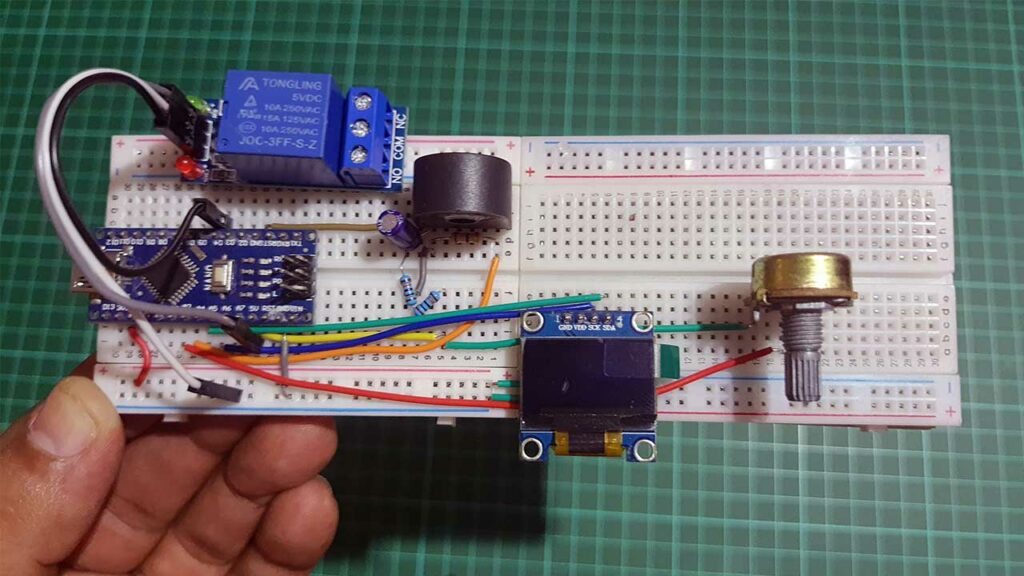
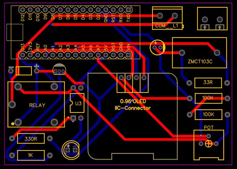
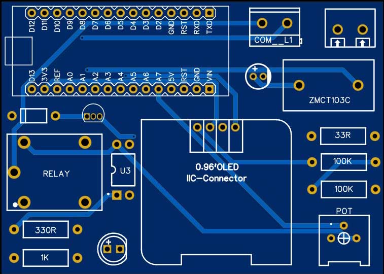
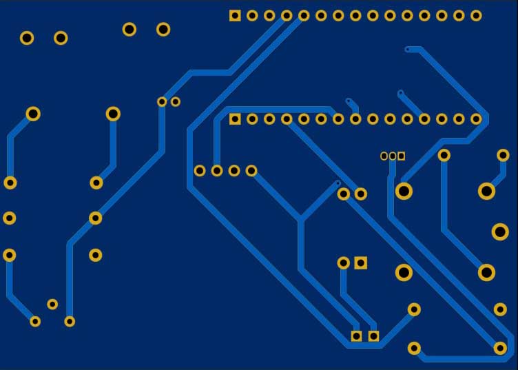
Lastly, you have the option to assemble this circuit on a breadboard for testing purposes, but I recommend using a custom PCB for a more stable setup. You can download the PCB Gerber file from the attached link.
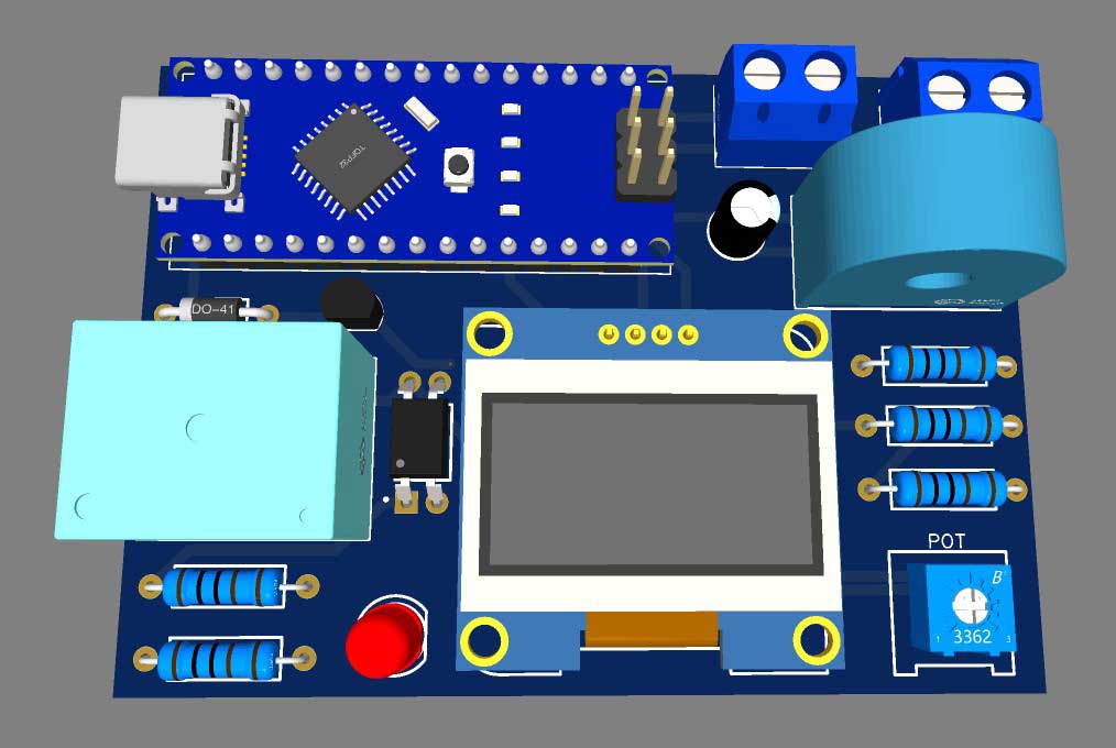
PCB Sponsored By PCBWay
I am excited to announce that this project has been made possible with the support and assistance from PCBWay. PCBWay is one of the most experienced PCB manufacturers in Global, and has specialized in the PCB and assembly industry.
You can visit the PCBWay official website by clicking here: PCBWay.com. So you will be directed to the PCBWay website.

You can now upload the Gerber File to the Website and place an order. The PCB quality is superb & high standard. That is why most people trust PCBWay for PCB & PCBA Services.
Additionally, PCBWay provides a convenient and free online PCB Gerber viewer, making it easier for you to review your PCB designs. You can access this tool here: PCBWay Free Online Gerber Viewer.
We’re grateful for PCBWay support in making this project a reality, and we encourage you to explore their services for your PCB needs.
Arduino Program Code
This is the Arduino Program code for the Overcurrent Protection Circuit using Arduino & CT Sensor. This code combines several components and libraries to create an overcurrent protection system with a current sensor (ZMCT103C), a relay, a potentiometer, and an OLED display. The full program code explanation is done below.
// EmonLibrary examples openenergymonitor.org, Licence GNU GPL V3

#include "EmonLib.h"                   // Include Emon Library
#include <Wire.h>
#include <Adafruit_GFX.h>
#include <Adafruit_SSD1306.h>
EnergyMonitor emon1;                   // Create an instance
int CT_pin = A3; // CT sensor pin connected to A3 pin of Arduino
int relayPin = 4; // Relay control pin connected to D4 pin of Arduino
int potPin = A2; // Potentiometer pin connected to A2 pin of Arduino

// OLED Display Settings
#define SCREEN_WIDTH 128 // OLED display width, in pixels
#define SCREEN_HEIGHT 64 // OLED display height, in pixels
#define SCREEN_ADDRESS 0x3C ///< See datasheet for Address; 0x3D for 128x64, 0x3C for 128x32
#define OLED_RESET     -1 // Reset pin # (or -1 if sharing Arduino reset pin)
Adafruit_SSD1306 display(SCREEN_WIDTH, SCREEN_HEIGHT, &Wire, OLED_RESET);

// Current Threshold and Hysteresis Values
double currentThreshold = 0; // Initial current threshold, in Amps
double hysteresis = 0.05; // Hysteresis value, in Amps

void setup()
{
  Serial.begin(9600);

  // initialize OLED display
  display.begin(SSD1306_SWITCHCAPVCC, SCREEN_ADDRESS);
  display.clearDisplay();
  display.setTextColor(WHITE);
  display.setTextSize(1);
  display.setCursor(0, 0);
  display.print("Over Current Protect");
  display.display();
  delay(1000);
  emon1.current(3, 32.59);             // Current: input pin, calibration.
  // Initialize Relay
  pinMode(relayPin, OUTPUT);
  digitalWrite(relayPin, LOW); // Initially turn the relay off
}

void loop() {
  // Measure Current
  double Irms = emon1.calcIrms(1480);

  // Display Current Value
  display.clearDisplay();
  display.setTextSize(1);
  display.setTextColor(SSD1306_WHITE);
  display.setCursor(0, 5);
  display.println("0-Current Protection");
  display.setTextSize(2);
  display.setCursor(0, 16);
  display.print("C:");
  display.print(Irms);
  display.println(" A");

  // Read Potentiometer Value and Set Current Threshold
  int potValue = analogRead(potPin);
  currentThreshold = map(potValue, 0, 1023, 0, 5000) / 1000.0;

  // Relay Control Based on Current Threshold and Hysteresis
  if (Irms > currentThreshold + hysteresis) {
    digitalWrite(relayPin, HIGH); // Turn Off the relay
  } else if (Irms < currentThreshold - hysteresis) {
    digitalWrite(relayPin, LOW); // Turn ON the relay
  }

  // Display Current Threshold and Relay Status
  display.print("CT:");
  display.print(currentThreshold);
  display.println(" A");
  display.print("Relay:");
  if (digitalRead(relayPin) == LOW) {
    display.println("ON");
  } else {
    display.println("OFF");
  }

  display.display(); // Update the OLED display
  delay(1000); // Update display every 1 second
}
Arduino Program Code Explanation
Here you can find a step-by-step program code explanation of the above Arduino code.
Include Libraries
This code includes several libraries that are necessary for its functionality. These libraries provide pre-written functions and code to interact with the components connected to the Arduino.
#include "EmonLib.h"                   // Include Emon Library
#include <Wire.h>
#include <Adafruit_GFX.h>
#include <Adafruit_SSD1306.h>
- `EmonLib.h`: This library is for energy monitoring and provides functions for measuring current.
- `Wire.h`: This library allows communication with I2C devices, like the OLED display.
- `Adafruit_GFX.h`: Part of the Adafruit graphics library, this library supports graphical functions for the OLED display.
- `Adafruit_SSD1306.h`: This library specifically supports the SSD1306 OLED display.
Global Variables
EnergyMonitor emon1; // Create an instance
– `EnergyMonitor emon1`: An instance of the EnergyMonitor class, which will be used to measure current.
int CT_pin = A3; // CT sensor pin connected to A3 pin of Arduino
int relayPin = 4; // Relay control pin connected to D4 pin of Arduino
int potPin = A2; // Potentiometer pin connected to A2 pin of Arduino
- `int CT_pin`: The analog pin (A3) to which the CT (Current Transformer) sensor is connected.
- `int relayPin`: The digital pin (D4) to which the relay control is connected.
- `int potPin`: The analog pin (A2) to which the potentiometer is connected.
OLED Display Setup
– Define the screen width and height for the OLED display.
// OLED Display Settings
#define SCREEN_WIDTH 128 // OLED display width, in pixels
#define SCREEN_HEIGHT 64 // OLED display height, in pixels
#define SCREEN_ADDRESS 0x3C ///< See datasheet for Address; 0x3D for 128x64, 0x3C for 128x32
#define OLED_RESET     -1 // Reset pin # (or -1 if sharing Arduino reset pin)
Adafruit_SSD1306 display(SCREEN_WIDTH, SCREEN_HEIGHT, &Wire, OLED_RESET);
– Create an instance of the Adafruit_SSD1306 class to initialize and communicate with the display using the Wire library.
Current Threshold and Hysteresis Values
– Define the initial current threshold as `0` Amps.
– Set the hysteresis value to `0.05` Amps. Hysteresis is used to prevent rapid relay switching when the current is near the threshold.
// Current Threshold and Hysteresis Values
double currentThreshold = 0; // Initial current threshold, in Amps
double hysteresis = 0.05; // Hysteresis value, in Amps
Setup Function
– Initialize serial communication for debugging at a baud rate of 9600.
Serial.begin(9600);
– Initialize the OLED display. If the initialization fails, the code enters an infinite loop.
  // initialize OLED display
  display.begin(SSD1306_SWITCHCAPVCC, SCREEN_ADDRESS);
  display.clearDisplay();
  display.setTextColor(WHITE);
  display.setTextSize(1);
  display.setCursor(0, 0);
  display.print("Over Current Protect");
  display.display();
  delay(1000);
– Initialize the EnergyMonitor instance (`emon1`) by specifying the CT sensor pin and a calibration value. Also, Initilize the Relay module.
  emon1.current(3, 32.59);             // Current: input pin, calibration.
  // Initialize Relay
  pinMode(relayPin, OUTPUT);
  digitalWrite(relayPin, LOW); // Initially turn the relay off
Loop Function
– Calculate the root-mean-square (RMS) current (`Irms`) using the `calcIrms` function from the EnergyMonitor library. This represents the current flowing through the CT sensor.
  // Measure Current
  double Irms = emon1.calcIrms(1480);
– Read the analog value from the potentiometer (`potPin`) and map it to a current threshold value between 0A and 5A. This allows you to manually adjust the current threshold using the potentiometer.
  // Read Potentiometer Value and Set Current Threshold
  int potValue = analogRead(potPin);
  currentThreshold = map(potValue, 0, 1023, 0, 5000) / 1000.0;
– Control the relay based on the current threshold and hysteresis. If the current exceeds the threshold plus hysteresis, the relay is turned on; if it falls below the threshold minus hysteresis, the relay is turned off.
  // Relay Control Based on Current Threshold and Hysteresis
  if (Irms > currentThreshold + hysteresis) {
    digitalWrite(relayPin, HIGH); // Turn Off the relay
  } else if (Irms < currentThreshold - hysteresis) {
    digitalWrite(relayPin, LOW); // Turn ON the relay
  }
– Display various information on the OLED display, including the current reading, the current threshold, hysteresis, and the status of the relay (ON or OFF).
  // Display Current Value
  display.clearDisplay();
  display.setTextSize(1);
  display.setTextColor(SSD1306_WHITE);
  display.setCursor(0, 5);
  display.println("0-Current Protection");
  display.setTextSize(2);
  display.setCursor(0, 16);
  display.print("C:");
  display.print(Irms);
  display.println(" A");
 // Display Current Threshold and Relay Status
  display.print("CT:");
  display.print(currentThreshold);
  display.println(" A");
  display.print("Relay:");
  if (digitalRead(relayPin) == LOW) {
    display.println("ON");
  } else {
    display.println("OFF");
  }
– Update the display every 1 second and repeat the loop.
  display.display(); // Update the OLED display
  delay(1000); // Update display every 1 second
This code essentially combines current monitoring, relay control, potentiometer-based threshold adjustment, and OLED display for visual feedback. It provides a functional overcurrent protection system that you can customize and expand upon as needed.
Demo: Overcurrent Protection Circuit using Arduino
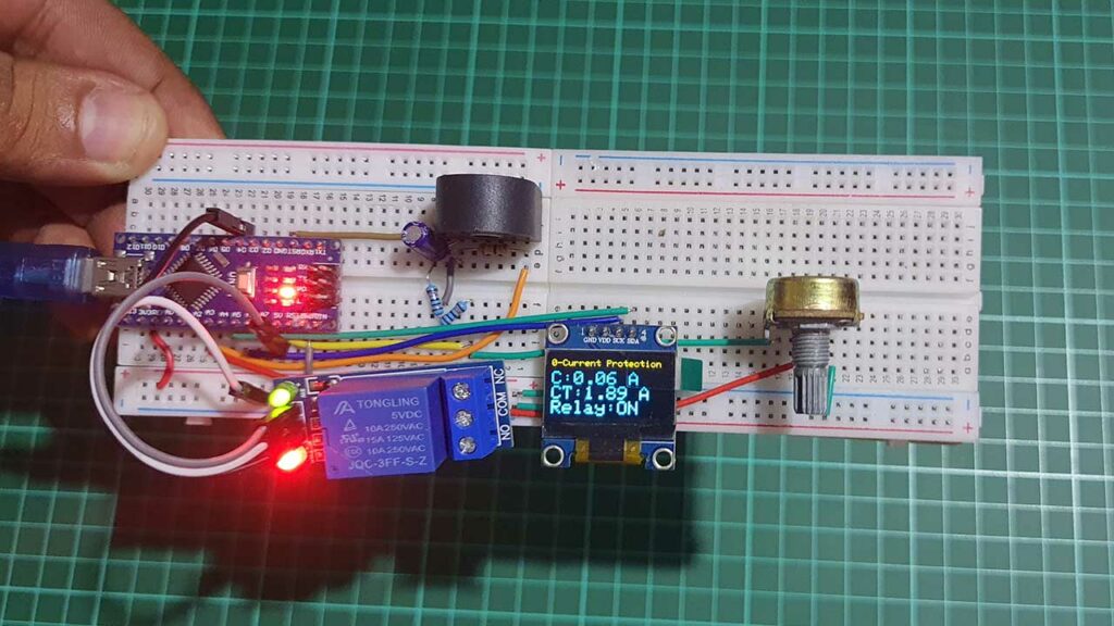
This project utilizes a ZMCT103C current sensor to measure electrical current, an Arduino with a 10k potentiometer to set a user-defined current threshold (with hysteresis), and a relay to control the circuit. The OLED display continuously presents real-time data, including current readings, the threshold, and relay status. When the current surpasses the threshold by a specific margin, the relay switches the circuit on, providing overcurrent protection, while the display offers user-friendly monitoring and control.
Conclusion
In summary, this project serves as an overcurrent protection system that allows users to set a specific current threshold. When the current surpasses this threshold by a specified amount (hysteresis), the relay is activated, and the connected circuit is powered. The OLED display provides crucial information and status updates, making it a user-friendly system for monitoring and protecting electrical circuits from excessive current.

