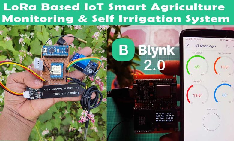
In this tutorial, you will learn how to make a LoRa based IoT Smart Agriculture Monitoring and Automatic Irrigation System using ESP8266 NodeMCU, Arduino Nano, and the new Blynk IoT 2.0 platform.
- Overview: LoRa based IoT Smart Irrigation & Monitoring System
- Components Required
- LoRa based IoT Smart Irrigation System Transmitter Circuit Diagram:
- LoRa based IoT Smart Irrigation System Receiver Circuit Diagram:
- Setting up Blynk 2.0 IoT Cloud Dashboard
- LoRa based IoT Smart Irrigation System with ESP8266 Transmitter and Receiver programming:
- Blynk IoT 2.0 Mobile application setup
- LoRa based Smart Agriculture Monitoring on Serial Monitor
- Project Demonstration: Video Tutorial & Guide
Overview: LoRa based IoT Smart Irrigation & Monitoring System
Here on the sensor node, we will use the Arduino Nano board and SX1278 LoRa-02 Transceiver module. Then we will interface multiple sensors like capacitive soil moisture sensor v1.2 to measure the quantity of water present in the soil. DS18B20 waterproof temperature sensor to measure the temperature of the soil. Similarly, In the cold season plants die due to fog and low temperature. Thus, DHT11/DHT22 Temperature & Humidity sensor is used to measure the temperature and humidity of surroundings. A 5V Single channel relay module and water Pump are used for an automatic irrigation system.
Previously, I had made an IoT Smart Agriculture Monitoring & Irrigation System. But, the area where I was working do not have WiFi Signals. My home is around 700/800 Meters away from the agricultural field. So, I couldn’t receive any WiFi signals there. Hence, I cannot monitor and control this device over the internet.
As said, “when there’s a will there’s a way“. I found these SX1278 LoRa transceiver modules laying around. So, I decided to use Arduino Nano, Capacitive soil moisture sensor, DHT22 sensor, DS18B20 sensor, 5 Volt relay, DC Water Pump, and SX1278 LoRa-02 module on the transmitter side. This LoRa Transmitter module will send the parameters like relative humidity of the soil, soil temperature, relative humidity, and temperature of surroundings wirelessly to the LoRa receiver.
On the receiver side, I have connected the SX1278 LoRa module to the NodeMCU ESP8266 module because it has a built-in wi-fi chip. So that LoRa receives the data and ESP8266 board uploads these parameters to the internet of things (IoT) server. As people suggested to me on the previous project, I decided to use the new Blynk IoT 2.0 Platform. Here I can monitor those data from anywhere in the world from web dashboards as well as a mobile application.
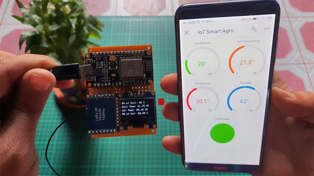
I also decided to use this small 0.96″ SSD1306 I2C OLED Display to Monitor Soil Moisture, soil temperature, relative humidity, and temperature locally on the receiver side.
Components Required
For this project, we need Arduino Nano, SX1278 LoRa Transceiver module, NodeMCU ESP8266 board, a capacitive soil moisture sensor, DS18B20 waterproof temperature sensor, DHT22 Temperature and Humidity sensor, 0.96-inch OLED display, 5 Volt single channel relay module, and a 5-volt dc pump motor. The motor is used for drawing water from the inlet and throwing water through the outlet. A pipe can be connected to it. You can purchase all these components from the Amazon link provided below.
| S.N | Components Name | Quantity | |
|---|---|---|---|
| 1 | NodeMCU ESP8266-12E Board | 1 | https://amzn.to/3sCrEbj |
| 2 | Capacitive Soil Moisture Sensor | 1 | https://amzn.to/3nyL9y7 |
| 3 | DHT22 Temperature & Humidity Sensor | 1 | https://amzn.to/32VEw1X |
| 4 | DS18B20 waterproof Temperature Sensor | 1 | https://amzn.to/33EkMQq |
| 5 | 0.96" I2C OLED Display | 1 | https://amzn.to/3kvENyc |
| 6 | Arduino Nano | 1 | https://amzn.to/3Hf7zvN |
| 7 | 5V Single-Channel Relay Module | 1 | https://amzn.to/3tBoAg2 |
| 8 | Few jumpers wires | 20 | https://amzn.to/3klh0A4 |
| 9 | LoRa SX1278 Transceiver Module | 1 | https://amzn.to/3G6xapO |
| 10 | 5V DC Water Pump | 1 | https://amzn.to/3GeRMfs |
*Please Note: These are affiliate links. I may make a commission if you buy the components through these links. I would appreciate your support in this way!
LoRa Module SX1278
The SX1278 Ra-02 Chip is manufactured by Semtech. The SX1278 RF module is mainly used for long-range spread spectrum communication. It can resist Minimizing current consumption & has a high sensitivity of -148 dBm with a power output of +20 dBm. A long transmission distance of almost 5km can be achieved with high reliability. Thus SX1278 is great for IoT applications to send sensor data to the cloud over long ranges.
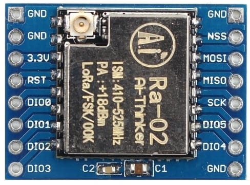
This module uses SX1278 IC from SEMTECH and works on a 433MHz frequency. Frequency hopping—which gives you that sweet balance of quality signal transmission will cover a range of 420-450 MHz. This long-range wireless capability is packed into a small (17 x 16mm) package and delivered without an antenna.
SX1278 Pinout
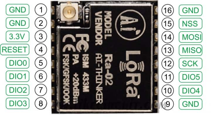
- ANT – This pin is to attach to the antenna.
- Pin 2, 9, 16: GND – Ground pin of common ground with power supply and controllers.
- Pin 3: 3.3V – To power up the device pin 3 will help for power input.
- RESET – Pin 4 is to reset the module through an external signal.
- Pin 5, 6, 7, 8, 10, 11: DIO0, DIO1, DIO2, DIO3, DIO4, DIO5 – To perform the general, I/O function through module the DIO pins will help. These pins is customizable as an interrupt pin.
- Pin 12: SCK – SCK pin is for the clock pulse during the SPI communication.
- Pin 13: MISO – MISO means Master in and Slave out that transfers data transfer from the Module to the Controller. The Master is a controller & SX1278 is Slave.
- Pin 14: MOSI – MOSI means Master out Slave In. So, this pin will receive the data from Controller.
- Pin 15: NSS – NSS is a chip select/enable pin will help to activate the slave.
LoRa Frequency Allocation
LoRa frequency is not legal everywhere. I am from Nepal and there is no regulation for the LoRa frequency range. But in India, the unlicensed Frequency range is from 865MHz to 867MHz. But, The SX1278 has a frequency of 433MHz so you are not allowed to use it for an extended time aside from for an academic purpose. Similarly, check the allowed Ranges in your country and confirm you’re allowed to use the actual frequency range.
LoRa based IoT Smart Irrigation System Transmitter Circuit Diagram:
This is a LoRa Transmitter Circuit Diagram. You can use the following connection table to assemble the components easily.
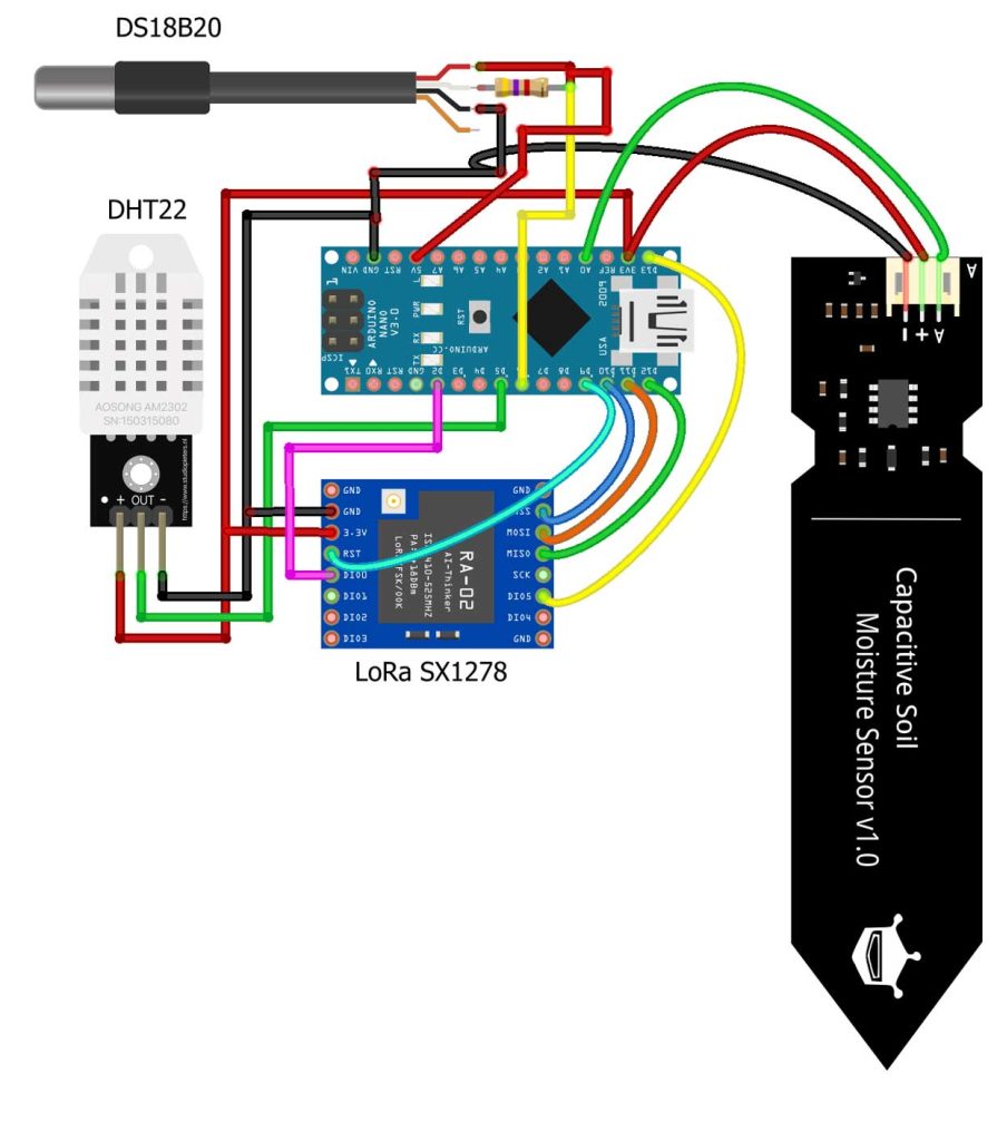

| LoRa SX1278 | Arduino Nano |
| GND | GND |
| 3.3V | 3.3V |
| NSS | D10 |
| MOSI | D11 |
| MISO | D12 |
| SCK | D13 |
| RST | D9 |
| DIO0 | D2 |
| Capacitive Soil Moisture | Arduino Nano |
| VCC | 3.3V |
| GND | GND |
| Analog | A0 |
| DHT11/22 | Arduino Nano |
| VCC | 3.3V |
| GND | GND |
| Signal | D5 |
| DS18B20 | Arduino Nano |
| VCC | 5V |
| GND | GND |
| Data | D6 |
| 4.7k ohm resistor | VCC & Data pin |
| 5V Relay Module | Arduino Nano |
| VCC | 5V |
| GND | GND |
| IN1 | D7 |
LoRa based IoT Smart Irrigation System Receiver Circuit Diagram:
This is a LoRa Receiver Circuit Diagram. You can easily assemble the components using the following connection table.
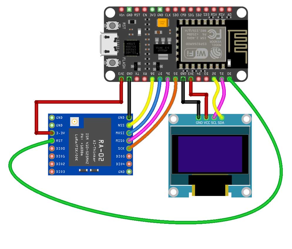
| SX1278 LoRa | ESP8266 NodeMCU |
| GND | GND |
| 3.3V | 3.3V |
| NSS | D8 |
| MOSI | D7 |
| MISO | D6 |
| SCK | D5 |
| RST | D0 |
| OLED Display | NodeMCU ESP8266 |
| GND | GND |
| VDD | 3.3V |
| SCK | D1 |
| SDA | D2 |
Project PCB Gerber File & PCB Ordering Online
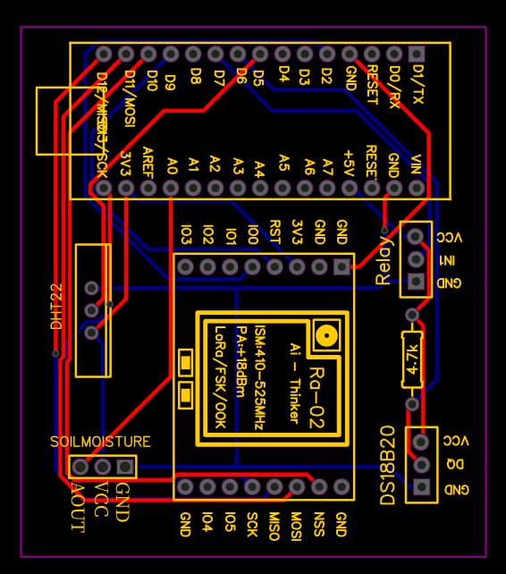
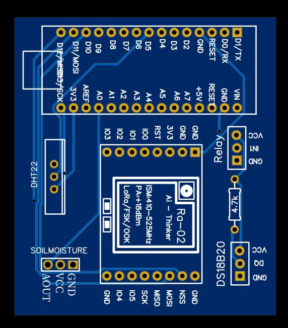
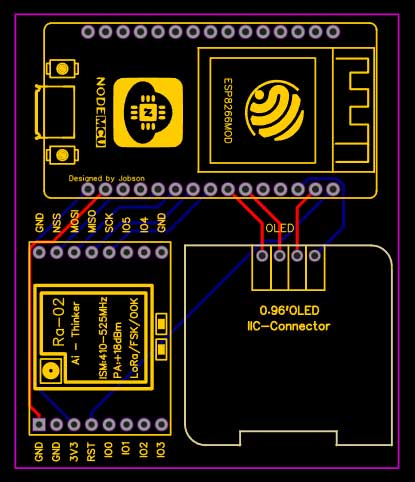
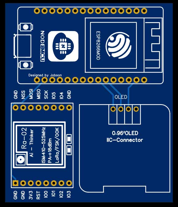
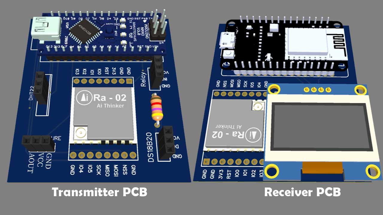
You can simply assemble the circuit on a breadboard. But To remove messy wiring and give a clean look, I designed a PCB prototype for this project. It is also helpful for troubleshooting without any errors. You can download the Gerber file of my PCB Design from the link attached below. The PCB looks like the image shown below.
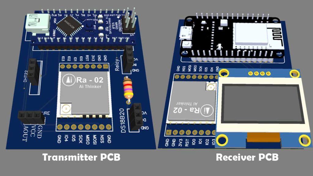
I provided the Gerber File for LoRa based IoT Smart Irrigation System with ESP8266 & Blynk 2.0 PCB below.
You can simply download the Gerber File and order your custom PCB from PCBWay

Visit the PCBWay official website by clicking here: https://www.PCBWay.com/. Simply upload your Gerber File to the Website and place an order. I prefer PCBWay for ordering custom PCBs. PCBWay is a place that brings manufacturers and customers together. They have more than a decade of experience in this field of fabrication, prototyping, and assembling PCBs. PCBWay have proved their focus to their customers’ needs in terms of cost-effectiveness, delivery, and quality. And this can be proved by their outstanding customer reviews.
Setting up Blynk 2.0 IoT Cloud Dashboard
First of all, Go to Blynk.cloud then sign in using your credentials. If you don’t have an account in Blynk. You have to click on Create an account. Provide necessary details and follow the instructions to create a new account.
Creating Blynk New template
A template is a project in which we can create a web and mobile dashboard for specific hardware. In our case, it’s an agriculture monitoring and automatic irrigation system. For creating a project, first, you have to click on the New Template.
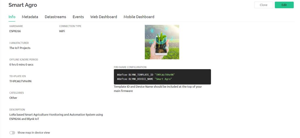
- Enter a template name. I am Giving it “Smart Agro”.
- Select the hardware board (ESP8266).
- The connection type will be wifi.
- You can add a description of your project if required.
- Click on Done.
- Now the template is created.
After that, you can choose a category according to your project. Don’t worry if you are not getting your category in this list you can choose others.
Here are two important things that you should remember one is template id and another one is device name which is required in the time of programming.
Creating New Blynk Datastream
A data stream is like a pipeline or channel. The data will be sent or received through these data channels.
In a single project or template, there can be multiple DataStream. In our project, we are receiving five data soil moisture, soil temperature, humidity and temperature of surroundings, and water pump. So in this project, we created Five DataStream.
Click on the new DataStream. Here are three options virtual pin, Enumerable, or any location. In our case, it is a virtual pin. Now you have to give a name for every data stream. After that, you have to choose virtual pins for DataStream. For Soil Moisture, Soil temperature, Temperature, Humidity, and Water Pump I choose virtual pins V1, V2, V3, V4, and V5 respectively.
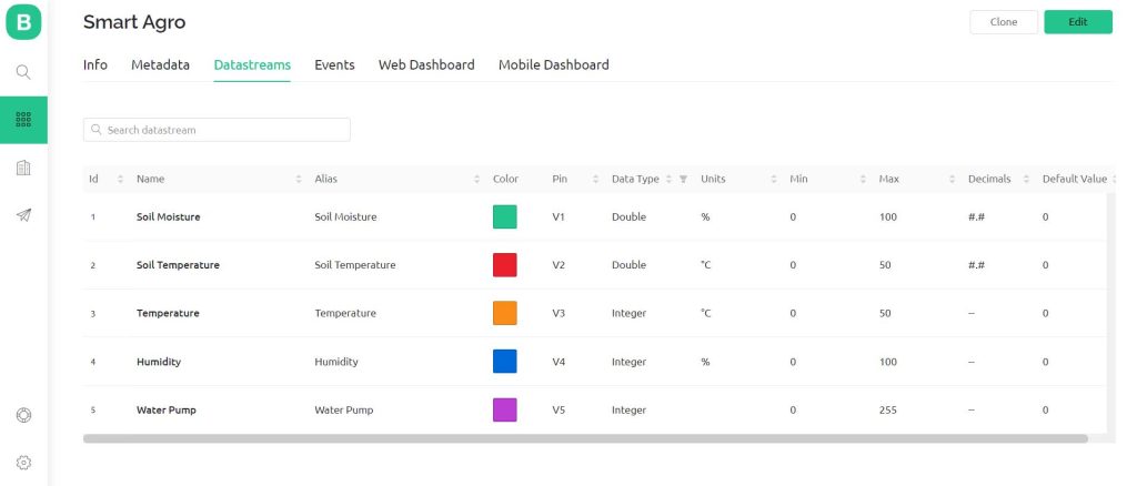
I choose the datatype as Double for Soil Moisture and Soil Temperature but an integer type for temperature, humidity, and water pump because they don’t have floating-point precision.
You also need to set units for DataStream as per the variable. I choose degree centigrade for soil temperature & air temperature. Then percentage for Soil Moisture & Humidity. Also, set the minimum and maximum values for the data streams.
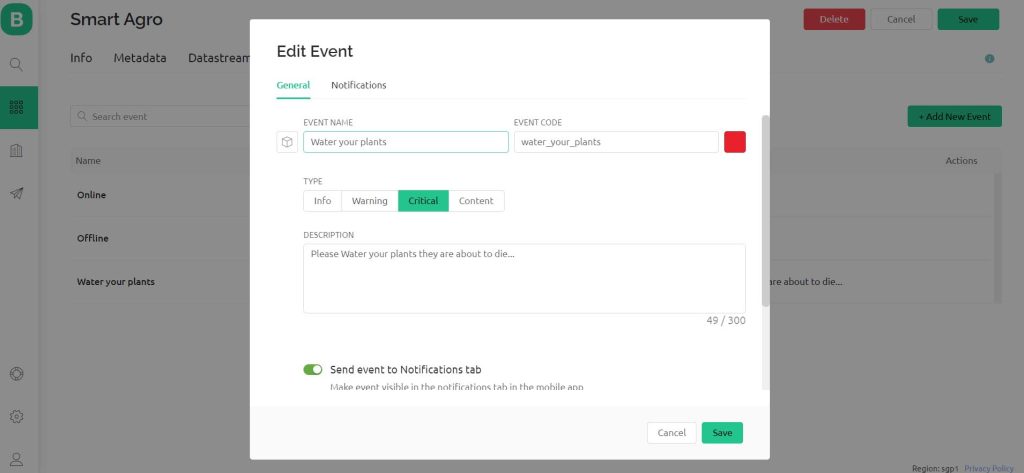
Creating Events on Blynk for Notification Alerts
Events are used for notification alert systems. So, here I am creating events to monitor soil moisture value. If the relative humidity of soil reaches below the threshold value an event is triggered and a notification is sent to your mobile phone.
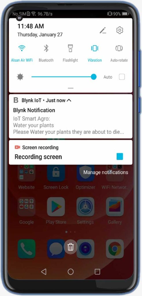
So to create an event:
- Click on add event.
- Enter the event Name. For me it’s “Water your plants“
- Choose your event color. I am selecting Red.
- Select the type of event. I am choosing Critical.
- Enter the description of your event.
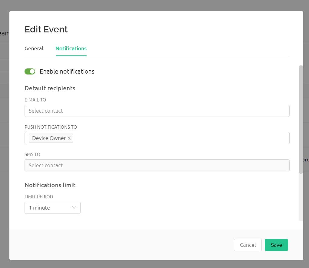
- Now go to notification tab then enable notification.
- then select push notification to device owner in every 1 minute.
- Click on save.
So, we have successfully created our first events.
Design the Blynk 2.0 Web Dashboard
After that move on to the web dashboard. In this section, you will be able to see some widgets for making your cool-looking web dashboard. But all the widgets are not free. You will get it all if you purchase their upgrade plan.
For showing the value of Soil Moisture, Soil Temperature, Temperature, and humidity of surroundings I will choose four Gauges. For Water Pump Indication I will use LED Widget. But, you can choose any widget according to your project.
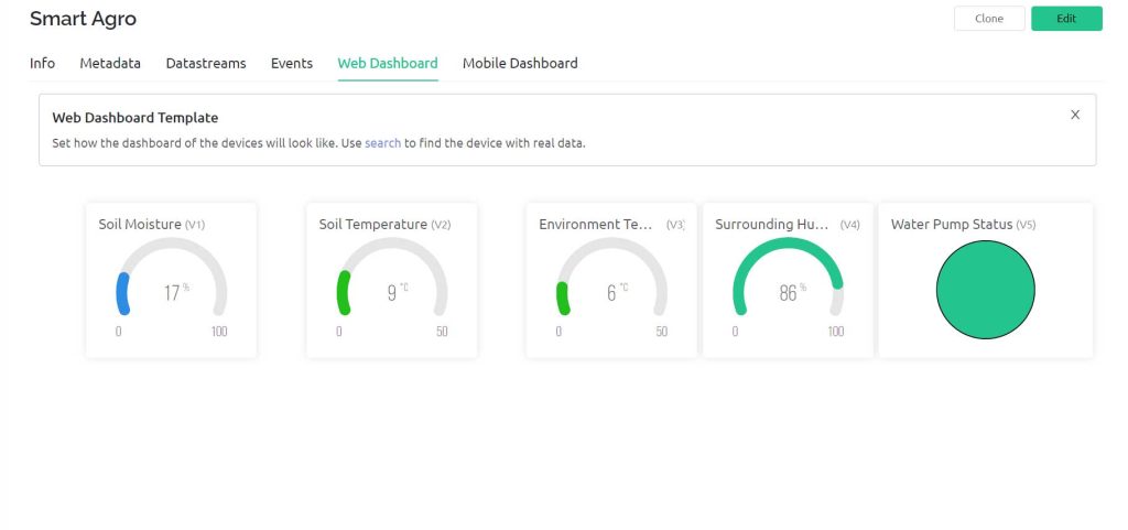
Now change the settings of the label. In settings, you have to give a name to the widget and you have to choose the data stream with which the widget will be connected.
After setting up the widgets click on the save button to save the entire project. That’s all for setting Blynk 2.0 IoT dashboard. We will set up Blynk 2.0 Mobile dashboard after uploading the program code.
LoRa based IoT Smart Irrigation System with ESP8266 Transmitter and Receiver programming:
To compile and upload these Transmitter and Receiver Program codes on respective boards, you need to install these libraries in Arduino IDE. You can always use the download link below or install them directly from Arduino IDE Library Manager.
- LoRa Library
- DHT.h Library
- DallasTemperature.h Library
- OneWire.h Library
- Blynk Library
- Adafruit_SSD1306.h Library
- Adafruit_Sensor.h Library
- Adafruit GFX.h Library
LoRa Transmitter Program Code
After installing all the required library files. You can upload the code provided below on Transmitter Module. Here on the transmitter side, we are using Arduino Nano. So, select the correct board and its COM port from the tools menu. Then upload the code.
#include <Wire.h>
#include <SPI.h>
#include <LoRa.h>
#include <DHT.h>
#include <OneWire.h>
#include <DallasTemperature.h>

#define DHTPIN 5          //pin where the dht22 is connected
DHT dht(DHTPIN, DHT22);
#define relay 7
#define ss 10
#define rst 9
#define dio0 2
#define ONE_WIRE_BUS 6
OneWire oneWire(ONE_WIRE_BUS);
DallasTemperature sensors(&oneWire);

String LoRaMessage = "";
int counter = 0;

const int AirValue = 590;   //you need to replace this value with Value_1
const int WaterValue = 300;  //you need to replace this value with Value_2
const int SensorPin = A0;
int soilMoistureValue = 0;
int soilmoisturepercent = 0;


void setup()
{
  Serial.begin(115200);
  dht.begin();
  sensors.begin(); // Dallas temperature
  pinMode(relay, OUTPUT);

  while (!Serial);
  Serial.println("LoRa Sender");
  LoRa.setPins(ss, rst, dio0);
    if (!LoRa.begin(433E6)) {
    Serial.println("Starting LoRa failed!");
    delay(100);
    while (1);
  }
}

void loop()
{
  soilMoistureValue = analogRead(SensorPin);  //put Sensor insert into soil
  soilmoisturepercent = map(soilMoistureValue, AirValue, WaterValue, 0, 100);
  float h = dht.readHumidity();
  float t = dht.readTemperature();
  sensors.requestTemperatures();
  float temp = sensors.getTempCByIndex(0);

  if (isnan(h) || isnan(t))
  {
  Serial.println("Failed to read from DHT sensor!");
  return;
  }
  Serial.print("Soil Moisture Value: ");
  Serial.println(soilMoistureValue);

  Serial.print("Soil Moisture: ");
  Serial.print(soilmoisturepercent);
  Serial.println("%");

  Serial.print("Soil Temperature: ");
  Serial.print(temp);
  Serial.println("°C");

  Serial.print("Temperature: ");
  Serial.print(t);
  Serial.println("°C");

  Serial.print("Humidity: ");
  Serial.print(h);
  Serial.println("%");
  Serial.println("");

  Serial.print("Sending packet: ");
  Serial.println(counter);

    if (soilmoisturepercent >= 0 && soilmoisturepercent <= 40)
  {
    Serial.println("Plants need water..., notification sent");
    digitalWrite(relay, LOW);
    Serial.println("Motor is ON");
    //WidgetLED PumpLed(V5);
    //PumpLed.on();
	 }
  else if (soilmoisturepercent > 30 && soilmoisturepercent <= 100)
  {
    Serial.println("Soil Moisture level looks good...");
    digitalWrite(relay, HIGH);
    Serial.println("Motor is OFF");
    //WidgetLED PumpLed(V5);
    //PumpLed.off();
  }

  LoRaMessage = String(counter) +"/" + String(soilMoistureValue) + "&" + String(soilmoisturepercent)
                + "#" + String(temp) + "@" + String(t) + "$" + String(h);

   // send packet
  LoRa.beginPacket();
  LoRa.print(LoRaMessage);
  LoRa.endPacket();

  counter++;

  delay(1500);
}
LoRa Receiver Program Code
In the LoRa Receiver program part, Go to File >> Examples >> Blynk >> Blynk.Edgent >> ESP8266_Edgent. Just copy the code provided below and paste it into your Arduino IDE ESP8266_Edgent page. Do not make any changes to other files. You just need to replace your Blynk Template ID and Blynk Device Name which is available in the blynk template.
// Fill-in information from your Blynk Template here
#define BLYNK_TEMPLATE_ID "TMPLxxxx"
#define BLYNK_DEVICE_NAME "IoT Smart Agro"

#define BLYNK_FIRMWARE_VERSION        "0.1.0"

#define BLYNK_PRINT Serial
//#define BLYNK_DEBUG

#define APP_DEBUG

// Uncomment your board, or configure a custom board in Settings.h
//#define USE_SPARKFUN_BLYNK_BOARD
#define USE_NODE_MCU_BOARD
//#define USE_WITTY_CLOUD_BOARD
//#define USE_WEMOS_D1_MINI

#include <SPI.h>
#include <LoRa.h>
#include <Adafruit_Sensor.h>
#include <Adafruit_GFX.h>
#include <Adafruit_SSD1306.h>
#include "BlynkEdgent.h"

#define ss 15
#define rst 16
#define dio0 4

#define SCREEN_WIDTH 128 // OLED display width, in pixels
#define SCREEN_HEIGHT 64 // OLED display height, in pixels
#define OLED_RESET -1 // Reset pin # (or -1 if sharing Arduino reset pin)
Adafruit_SSD1306 display(SCREEN_WIDTH, SCREEN_HEIGHT, &Wire, OLED_RESET);

String counter;
String soilMoistureValue;
String soilmoisturepercent;
String soiltemp;
String temperature;
String humidity;

void setup() {
  Serial.begin(115200);
  BlynkEdgent.begin();
  while (!Serial);

  Serial.println("LoRa Receiver");

  LoRa.setPins(ss, rst, dio0);

  if (!LoRa.begin(433E6)) {
    Serial.println("Starting LoRa failed!");
    while (1);
  }
  display.begin(SSD1306_SWITCHCAPVCC, 0x3C); //initialize with the I2C addr 0x3C (128x64)
  display.clearDisplay();
}

void loop() {
  BlynkEdgent.run();
  // try to parse packet
  int pos1, pos2, pos3, pos4, pos5;
  int packetSize = LoRa.parsePacket();
  if (packetSize)
  {
    // received a packet
    Serial.print("Received packet:  ");
    String LoRaData = LoRa.readString();
    Serial.print(LoRaData);
    // read packet
    while (LoRa.available()) {
      Serial.print((char)LoRa.read());
    }
    // print RSSI of packet
    Serial.print("' with RSSI ");
    Serial.println(LoRa.packetRssi());

    pos1 = LoRaData.indexOf('/');
    pos2 = LoRaData.indexOf('&');
    pos3 = LoRaData.indexOf('#');
    pos4 = LoRaData.indexOf('@');
    pos5 = LoRaData.indexOf('$');

    counter = LoRaData.substring(0, pos1);
    soilMoistureValue = LoRaData.substring(pos1 + 1, pos2);
    soilmoisturepercent = LoRaData.substring(pos2 + 1, pos3);
    soiltemp = LoRaData.substring(pos3 + 1, pos4);
    temperature = LoRaData.substring(pos4 + 1, pos5);
    humidity = LoRaData.substring(pos5 + 1, LoRaData.length());

    //send data to blynk
    Blynk.virtualWrite(V1, soilmoisturepercent); //Soil Moisture
    Blynk.virtualWrite(V2, soiltemp); //Soil Temperature
    Blynk.virtualWrite(V3, temperature);  // for Temperature
    Blynk.virtualWrite(V4, humidity);  //for Humidity

    Serial.print(F("Packet No = "));
    Serial.println(counter);

    Serial.print(F("Soil Moisture: "));
    Serial.print(soilmoisturepercent);
    Serial.println(F("%"));

    Serial.print(F("Soil Temperature: "));
    Serial.print(soiltemp);
    Serial.println(F("°C"));

    Serial.print(F("Temperature: "));
    Serial.print(temperature);
    Serial.println(F("°C"));

    Serial.print(F("Humidity = "));
    Serial.print(humidity);
    Serial.println(F("%"));

    Serial.print("Soil Moisture Value: ");
    Serial.print(soilMoistureValue);

    Serial.println();

    if (soilmoisturepercent.toInt() > 100)
    {
      display.clearDisplay();

      // display Soil Humidity
      display.setTextColor(WHITE);
      display.setTextSize(1);
      display.setCursor(0, 5);
      display.print("RH of Soil: ");
      display.print("100");
      display.print(" %");

      // display soil temperature
      display.setCursor(0, 20);
      display.print("Soil Temp: ");
      display.print(soiltemp);
      display.print(" ");
      display.cp437(true);
      display.write(167);
      display.print("C");

      // display air temperature
      display.setCursor(0, 35);
      display.print("Air Temp: ");
      display.print(temperature);
      display.print(" ");
      display.cp437(true);
      display.write(167);
      display.print("C");

      // display relative humidity of Air
      display.setCursor(0, 50);
      display.print("RH of Air: ");
      display.print(humidity);
      display.print(" %");

      display.display();
      delay(1500);
    }
    else if (soilmoisturepercent.toInt() < 0)
    {
      display.clearDisplay();

      // display Soil Humidity
      display.setTextColor(WHITE);
      display.setTextSize(1);
      display.setCursor(0, 5);
      display.print("RH of Soil: ");
      display.print("0");
      display.print(" %");

      // display soil temperature
      display.setCursor(0, 20);
      display.print("Soil Temp: ");
      display.print(soiltemp);
      display.print(" ");
      display.cp437(true);
      display.write(167);
      display.print("C");

      // display air temperature
      display.setCursor(0, 35);
      display.print("Air Temp: ");
      display.print(temperature);
      display.print(" ");
      display.cp437(true);
      display.write(167);
      display.print("C");

      // display relative humidity of Air
      display.setCursor(0, 50);
      display.print("RH of Air: ");
      display.print(humidity);
      display.print(" %");

      display.display();
      delay(1500);
    }
    else if (soilmoisturepercent.toInt() >= 0 && soilmoisturepercent.toInt() <= 100)
    {
      display.clearDisplay();

      // display Soil humidity
      display.setTextColor(WHITE);
      display.setTextSize(1);
      display.setCursor(0, 5);
      display.print("RH of Soil: ");
      display.print(soilmoisturepercent);
      display.print(" %");

      // display soil temperature
      display.setCursor(0, 20);
      display.print("Soil Temp: ");
      display.print(soiltemp);
      display.print(" ");
      display.cp437(true);
      display.write(167);
      display.print("C");

      // display air temperature
      display.setCursor(0, 35);
      display.print("Air Temp: ");
      display.print(temperature);
      display.print(" ");
      display.cp437(true);
      display.write(167);
      display.print("C");

      // display relative humidity of Air
      display.setCursor(0, 50);
      display.print("RH of Air: ");
      display.print(humidity);
      display.print(" %");

      display.display();
      delay(1500);
    }
    if (soilmoisturepercent.toInt() >= 0 && soilmoisturepercent.toInt() <= 30)
    {
      Serial.println("needs water, send notification");
      //send notification
      Blynk.logEvent("water_your_plants", "Please Water your plants they are about to die...") ;
      Serial.println("Motor is ON");
      Blynk.virtualWrite(V5, 255);
      delay(1000);
    }
    else if (soilmoisturepercent.toInt() > 30 && soilmoisturepercent.toInt() <= 100)
    {
      Serial.println("Soil Moisture level looks good...");
      Serial.println("Motor is OFF");
      Blynk.virtualWrite(V5, 0);
      delay(1000);
    }

  }
}
Simply after making necessary changes upload the code to NodeMCU ESP8266 12E Board.
Also, check:
- LoRa based Wireless weather station
- Capacitive soil moisture sensor with Arduino & OLED
- Arduino Wireless communication with NRF24L01
Blynk IoT 2.0 Mobile application setup
Download the blynk application into your mobile.
- New Blynk Mobile App (Android)
- New Blynk Mobile App (iOS)
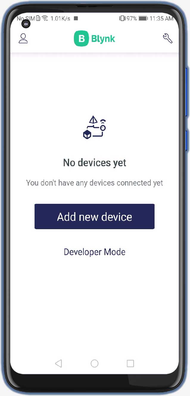
After installing the application login into your account. Turn on the developer mode if it is not turned on by going into your profile.
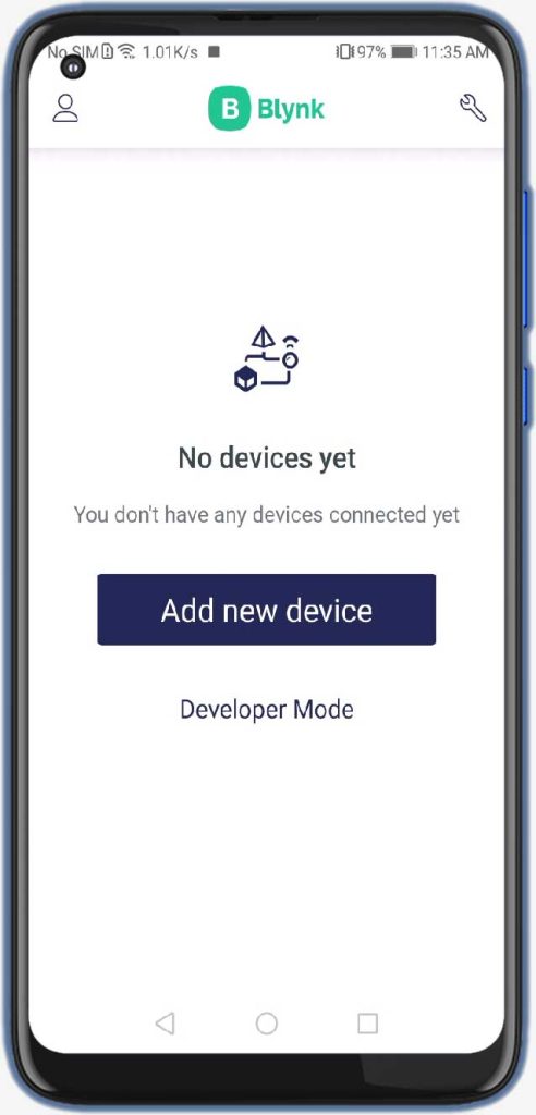
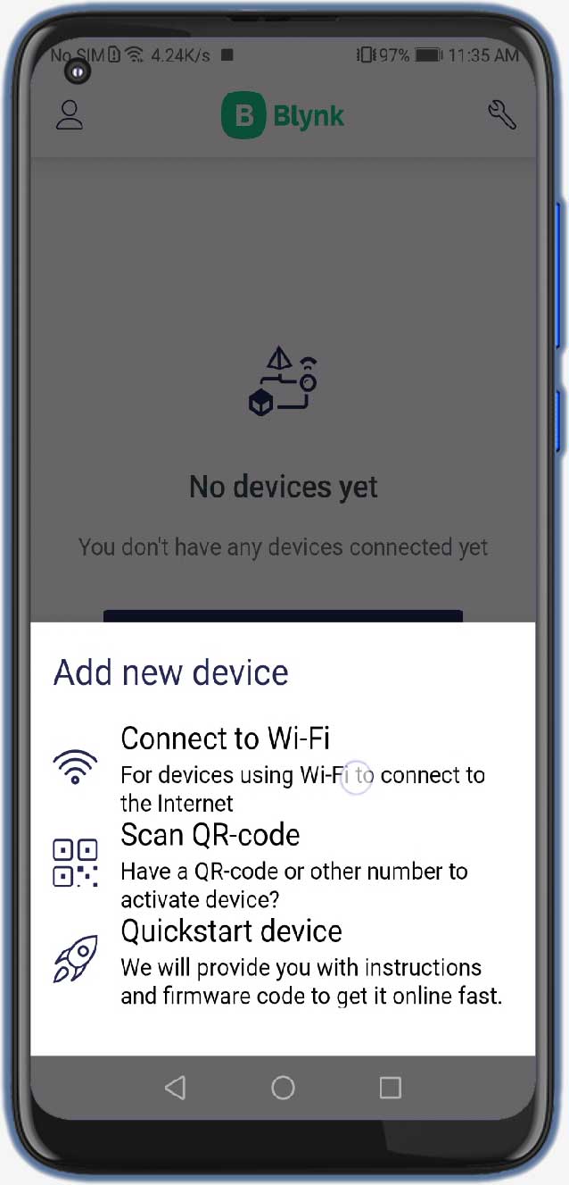
- Click on Add new device
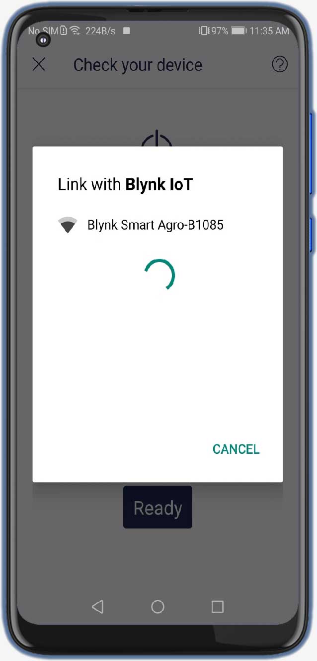
- Click on Ready
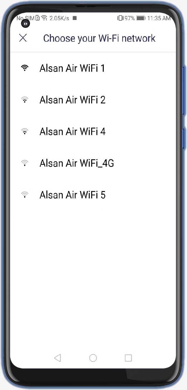
- Choose the wifi which is created by the NodeMCU
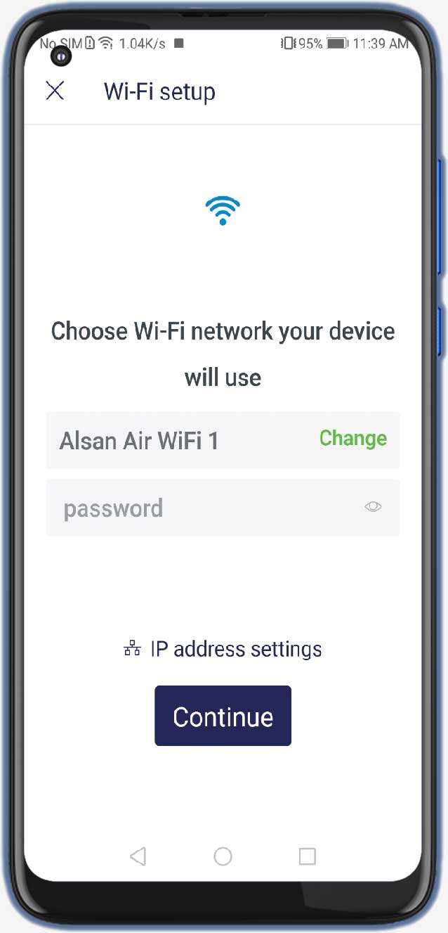
- Give the wifi credentials of the router with which you want to connect the NodeMCU
- Click on Continue
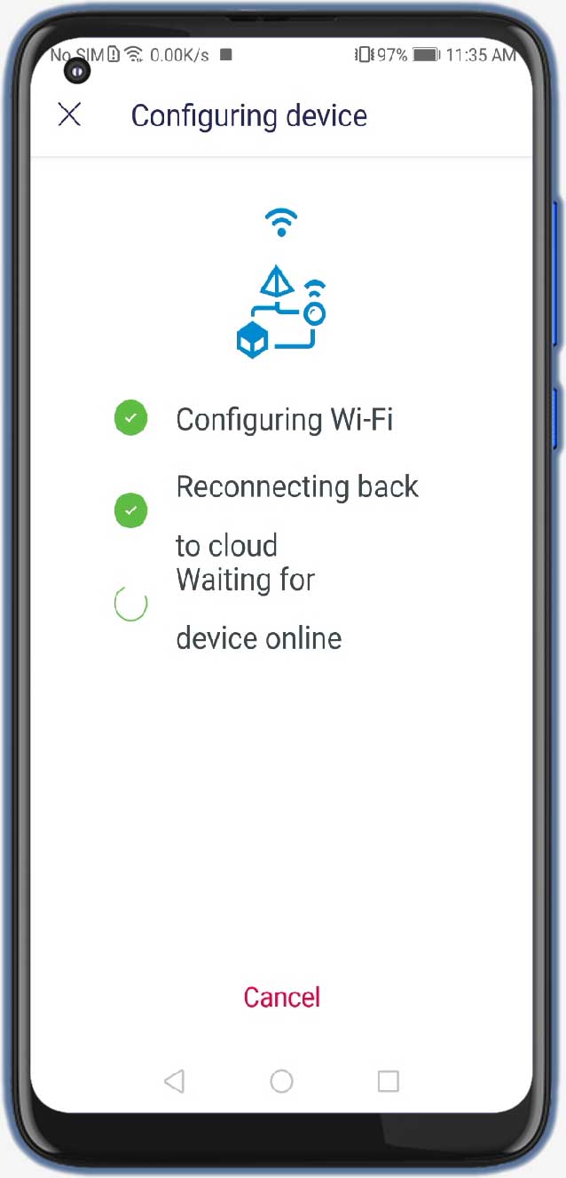
- Now the board will connect to the router if the given wifi credentials are true
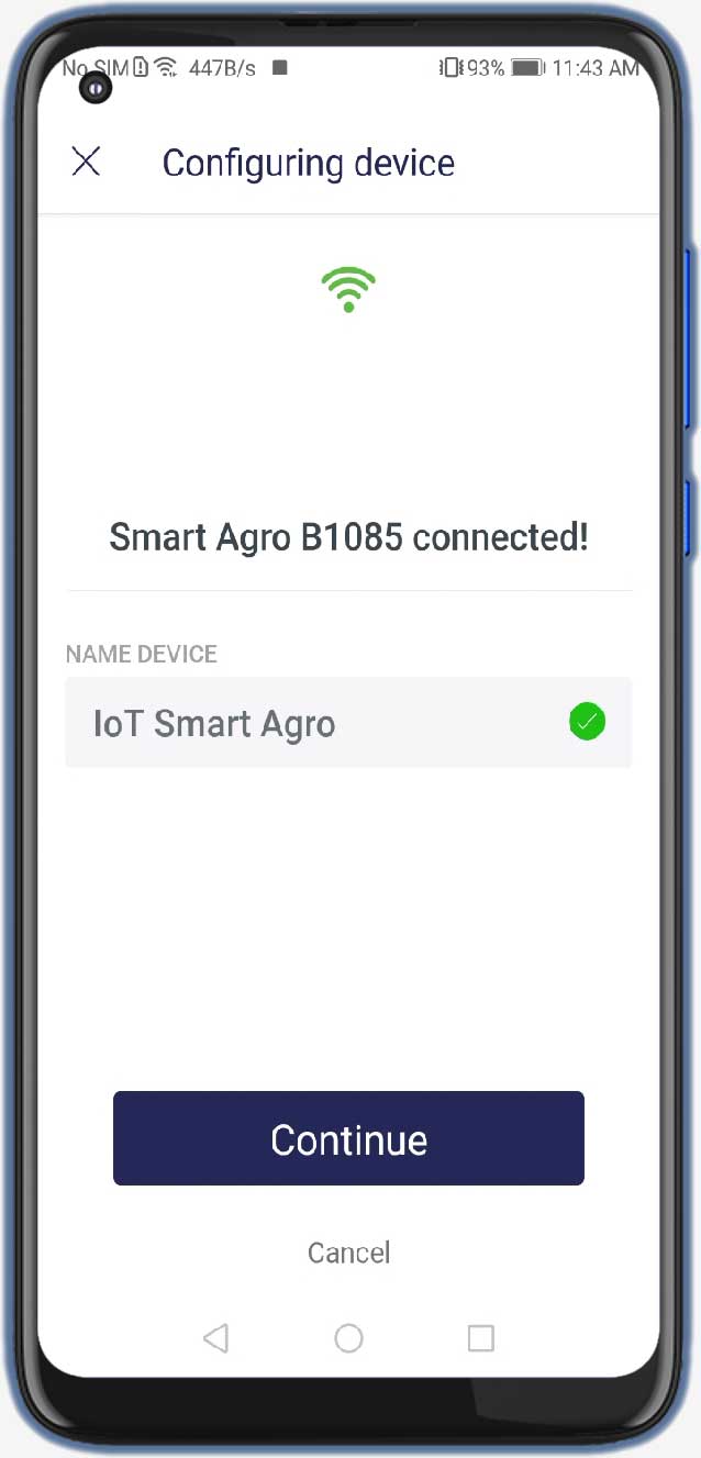
- Click on –> Continue
- Provide your Device Name and click Continue
- Select your Template then click on Done
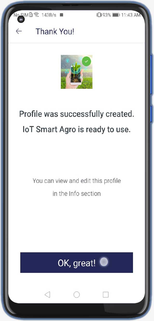
- –> OK, great! –> Finish and exit.
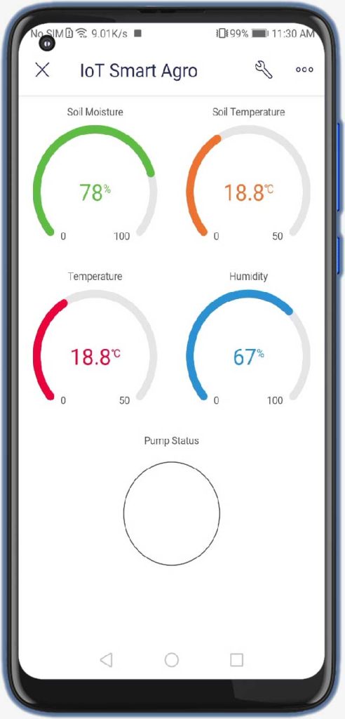
So, that’s all for the Mobile dashboard setup. Now you can see the data of your blynk device into your mobile app and in the web dashboard as well.
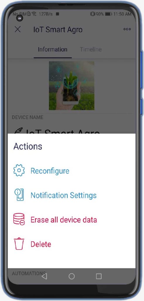
Reconfiguring wi-fi credentials on device without hardcoding
To reconfigure the wifi credentials on the new blynk platform you don’t have to hardcode the device. Under device settings, choose the reconfigure device option to reconfigure your device to the new WiFi network.
Alternately, You can also press the flash button on NodeMCU for 10 seconds to erase WiFi credentials from EEPROM. Then you can reconfigure the wifi credentials again by adding it as a new device.

LoRa based Smart Agriculture Monitoring on Serial Monitor
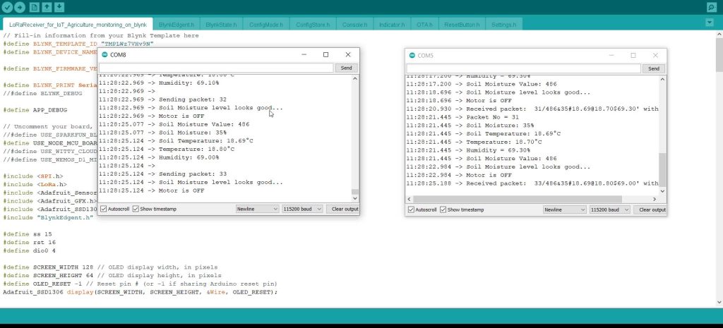
After, uploading both Transmitter and Receiver Program codes to the respective boards & Configuring the device on New Blynk IoT Application. You can also monitor those data through a serial monitor. Connect both boards to your PC and select their respective COM port to open the Serial Monitor at the baudrate of 115200. Here, you can see the real-time data transmitted and received through LoRa.
Project Demonstration: Video Tutorial & Guide
So now I have powered the complete system. On the Receiver Node, This little OLED Display displays the Relative Humidity of Soil, Soil Temperature, Air Temperature, and Relative Humidity of Air. Whereas in the Blynk application you can see the soil moisture sensor readings. You can see the temperature of soil and air. Similarly, you can also see the relative humidity of Air. Then you will find a LED status for the Water Pump.

First of all, let me test the soil moisture sensor. Here I am taking a cup of water to test this soil moisture sensor. Let me dip the sensor inside the water so you can see the reading Increasing. So, when I remove this sensor from the water you can see the percentage decreasing.
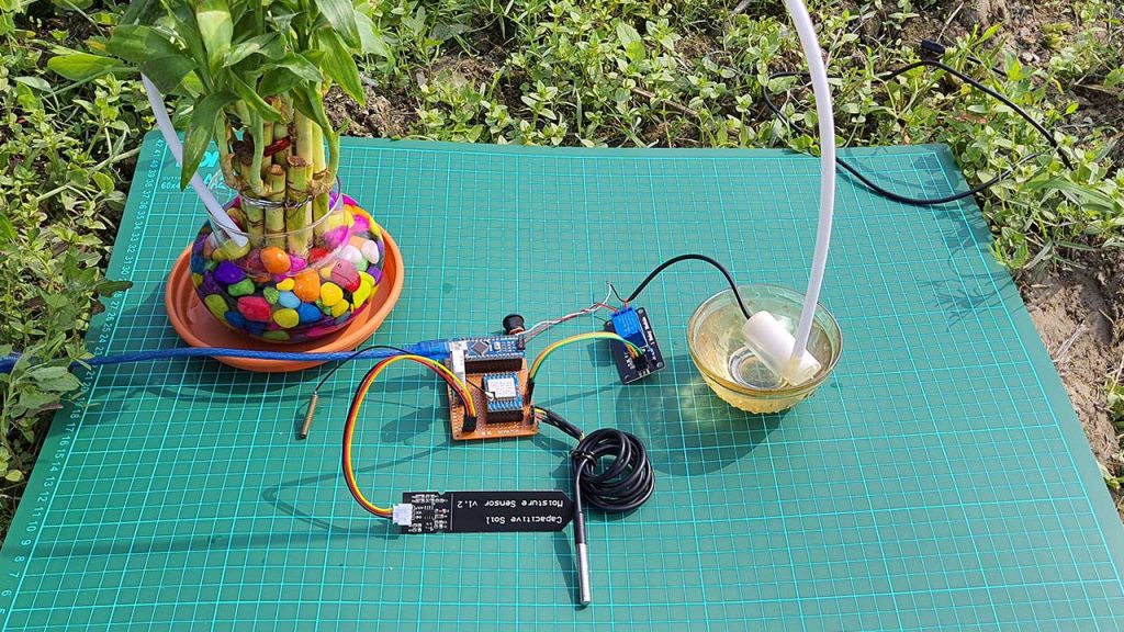
As the soil moisture decreases, the relay is turned ON automatically. You can also see the Water pump LED glowing on the blynk app. At the same time, you will also receive a notification on your mobile phone.

Similarly, you can also monitor the other two sensors’ data from anywhere in the world using this new blynk 2.0 IoT Platform.

The Video Tutorial & Guide of this project is available on The IoT Projects Youtube Channel.

Hi need help in project plz call 9923257011 or send me your phone number
Sir can you make a project for us as per our choice for FYP.
Great write up! Thanks for sharing with the IOT community.
How do you think this could developed into a deployable system? How could you make an enclosure to protect the device?
Please join me on my new blog heraldoftechnolgy.com where I am sharing similar IOT projects.
PCB design is correct power supply for each sensor