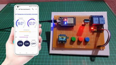
Today’s world is in search of comfort, making IoT devices is the best way to make life easier. It allows us to control home appliances, door-locks, machines using a smartphone or webserver. Here, we are doing the same using the Android app designed by the MIT App Inventor. So today’s project is all bout Home Automation with MIT App Inventor and ESP8266. Previously, we used the Blynk Android app to control home devices.
What is MIT App Inventor?
MIT App Inventor is an open-source website for Android. It was originally created by Google but is now maintained by the Massachusetts Institute of Technology (MIT). Even a beginner using MIT App Inventor can easily create applications for Android. The MIT App Inventor uses a GUI (graphical interface), in which users can drag and drop visual objects to create apps that can be easily run on Android devices.

After designing an entire app on MIT app inventor, you can download it on your Android phone using the QR code. furthermore, you can download its APK file on your PC and later install it on your smartphone. finally, we will interface the app to ESP8266 and control the home appliances.
Components Required
Following are the list of the components required for making home automation project using MIT App Inventor and NodeMCU ESP8266.
- NodeMCU ESP8266
- Lamp
- 5V Relay
- Jumper Wires
Relay Module
A relay is an electrically operated switch. Relays are used for controlling multiple circuits by one signal. So using relays we can turn the circuit “ON” and “OFF” with electricity. The relay is controlled by a small current (5v) and can switch “ON” and “OFF” the large current. Typically, the relay has five terminals as shown below:
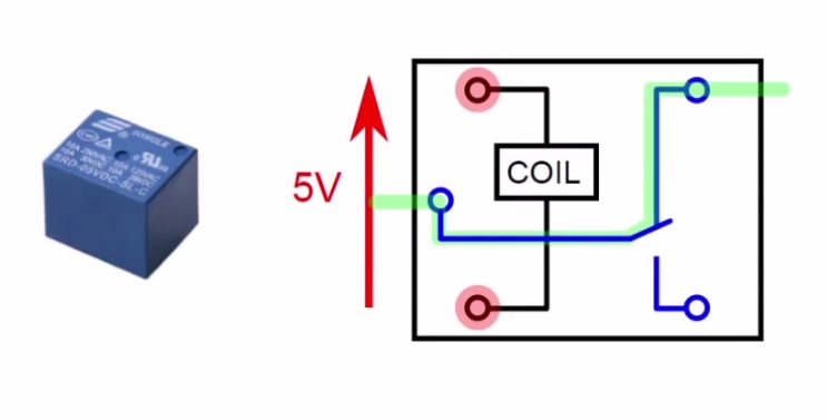
When no voltage is applied to the coil, the COM terminal will be connected to the NC (Normally Closed) terminal. And when voltage is applied to the coil, an electromagnetic field is produced that attracts the armature, and a COM and NO (Normally Open) terminal connection is made, which allows for very large currents.
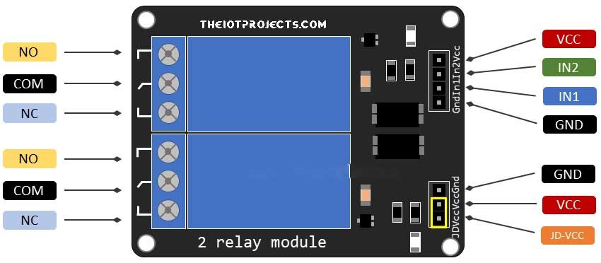
A small driver circuit with a transistor, diode, and a resistor is used to configure relay. The transistor is used to amplify the current, the resistor is used to provide BIAS to the transistor, and if the transistor is off, the diode is used to stop the reverse current flow. Here we have used the 5V relay module for demonstration.
Circuit Diagram: Home Automation with MIT App Inventor & ESP8266
Wiring these components are easy. You can follow the below circuit diagram and the pin connection table to assemble your circuit.
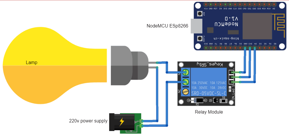
| NodeMCU | Relay |
| Vcc | Vcc |
| GND | GND |
| D4 | Input |
Now we have to make an Android APP using MIT App Inventor for controlling home appliances.
Create an Android app using MIT App Inventor
We will now create an Android app using MIT App Inventor to control lighting using the following steps.
- First go to the MIT Application Inventor website: http://ai2.appinventor.mit.edu/
- Then click ‘Create Applications‘ in the top left corner.

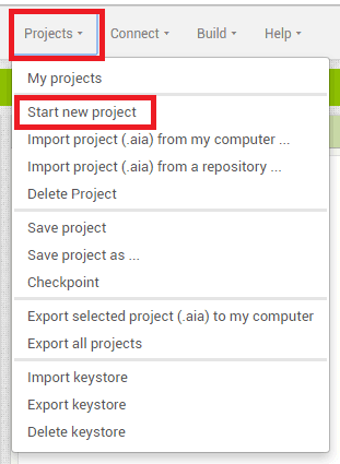
- Now click on ‘Projects‘ on the next screen and then ‘Start a new project‘.
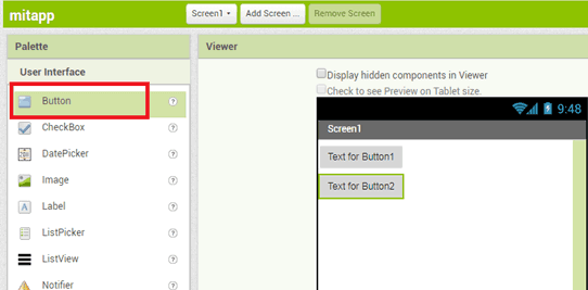
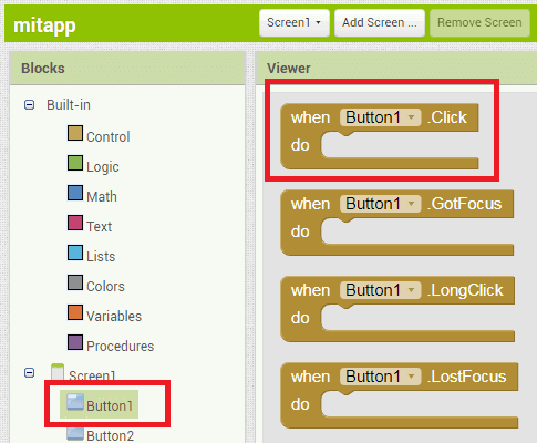
- Now click on ‘Button‘ and drag and drop two buttons on the main screen. You can enter your favorite name in the button from the options on the right.
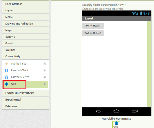
- Then click ‘Connectivity‘ and drag and drop the web component to the main screen.
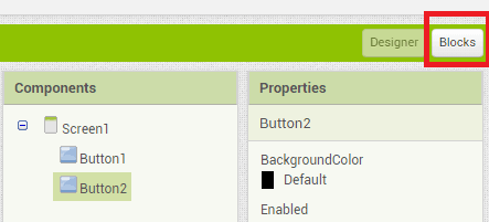
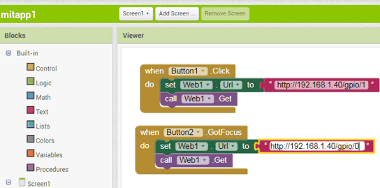
- Click ‘Blocks‘ now to add blocks to your application.
- Now click on button 1 in the block menu and then click on the marked red option.
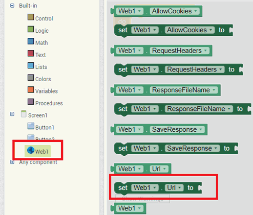
- After this click on Web 1. Scroll down and select the red marked block.
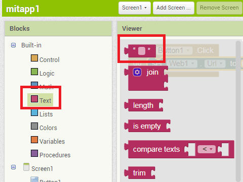
- Now click on the text menu and choose the first option. Enter your URL in the text menu.
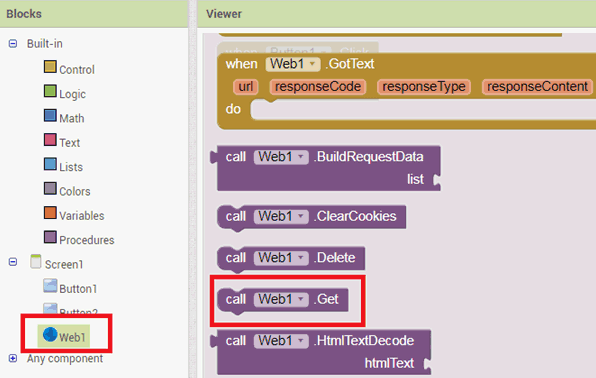
- Then click on Web 1 again and then select the marked red option.
- Follow the same procedure for ‘Button 2′.
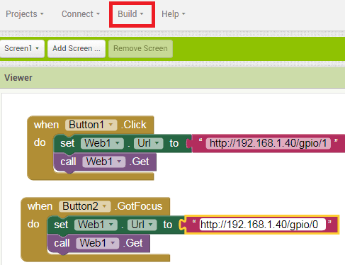
- Now that the app is ready to download, click on ‘Build’ to get the simple apk file. Also, there are two options to download the app APK, by QR code and directly on PC, then install it on Android.
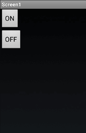
- Now your app is ready, and you can control the lighting using the ON-OFF button presented in the app.
Now we have to upload the code to NodeMCU to create a simple HTTP web server for controlling home applications. We will use the HTTP GET method for communicating between ESP8266 and Android applications.
Programming Code Explanation
Below we explain the function of the code so that you can understand how the code actually works. The full code for the project to control home appliances using the MIT designed Android app is provided at the end.
I Include the libraries for the ESP8166 WiFi module, and enter the WiFi Credentials like SSID and Password.
#include <ESP8266WiFi.h>
const char* ssid = "xxxxxxxx";
const char* password = "xxxxxxxxx";
Serial Monitor is started at the default Baud Rate for NodeMCU
Serial.begin(115200);Relay Pin is defined to NodeMCU D4 pin i.e. GPIO pin 2.
pinMode(2, OUTPUT);
  digitalWrite(2, 0);
In the void setup function, the function will try to connect to WiFi. This process executes in a loop, which means it runs until there is a connection to WiFi. So be careful before entering your WiFi SSID and Password.
void setup() {
 // Connect to WiFi network
  Serial.println();
  Serial.println();
  Serial.print("Connecting to ");
  Serial.println(ssid);
  WiFi.begin(ssid, password);
  while (WiFi.status() != WL_CONNECTED) {
    delay(500);
    Serial.print(".");
  }
  Serial.println("");
  Serial.println("WiFi connected");
In void loop, itCheck if a client has connected. It Wait until the client sends some data and performs tasks according to input.
void loop() {
  WiFiClient client = server.available();
  if (!client) {
    return;
  }
  Serial.println("new client");
  while(!client.available()){
    delay(1);
  }
  String req = client.readStringUntil('r');
Now navigate through your browser to check if your web server is working perfectly. Use the following URLs to turn your light ON or OFF.
Note: 192.168.1.40 is the IP address of NodeMCU. You can find the IP address of your NodeMCU on Serial Monitor. When you run the code on the Arduino IDE, it prints your device’s IP address on the serial monitor. Therefore, it will confirm whether the webserver is working or not.
Final Code for Home Automation with MIT App Inventor and ESP8266
The below code is the final program code of this project. Simply copy the code, choose your ESP8266 NodeMCU board, and correct port on Arduino IDE. Now Compile the code and upload it to the NodeMCU board.
#include <ESP8266WiFi.h>

const char* ssid = "Enter Your WiFi Name ";
const char* password = "Enter Your WiFi Password";


WiFiServer server(80);

void setup() {
  Serial.begin(115200); //Default Baud Rate for NodeMCU
  delay(10);


  pinMode(2, OUTPUT);  // Connect Relay to NodeMCU's D4 Pin
  digitalWrite(2, 0);

  // Connect to WiFi network
  Serial.println();
  Serial.println();
  Serial.print("Connecting to ");
  Serial.println(ssid);

  WiFi.begin(ssid, password);

  while (WiFi.status() != WL_CONNECTED) {
    delay(500);
    Serial.print(".");
  }
  Serial.println("");
  Serial.println("WiFi connected");

  // Start the server
  server.begin();
  Serial.println("Server started");

  // Print the IP address
  Serial.println(WiFi.localIP());
}

void loop() {
  // Check if a client has connected
  WiFiClient client = server.available();
  if (!client) {
    return;
  }

  // Wait until the client sends some data
  Serial.println("new client");
  while(!client.available()){
    delay(1);
  }


  String req = client.readStringUntil('r');
  Serial.println(req);
  client.flush();

  int val;
  if (req.indexOf("/gpio/0") != -1)
    val = 0;
  else if (req.indexOf("/gpio/1") != -1)
    val = 1;
  else {
    Serial.println("invalid request");
    client.stop();
    return;
  }

  // Set GPIO2 according to the request
  digitalWrite(2, val);

  client.flush();

  String s = "HTTP/1.1 200 OKrnContent-Type: text/htmlrnrn<!DOCTYPE HTML>rn<html>rnGPIO is now ";
  s += (val)?"high":"low";
  s += "</html>
Conclusion
In this way, you can control home appliances or any electronic devices using this IoT based Android app. Also, check out our previous home automation project using the ESP Webserver and Google Firebase.


missing terminating ” character
below is OK last three lines
s += (val)?”high”:”low”;
s += “”
}
I believe the following is required at end client.println(s);
So this is what it should be
String s = “HTTP//10.0.0.47 200 OK\r\nContent-Type: text/html\r\n\r\n\r\n\r\nGPIO is now “;
s += (val) ? “high” : “low”;
s += “”;
client.println(s);
Sorry that was a mistake on my part.