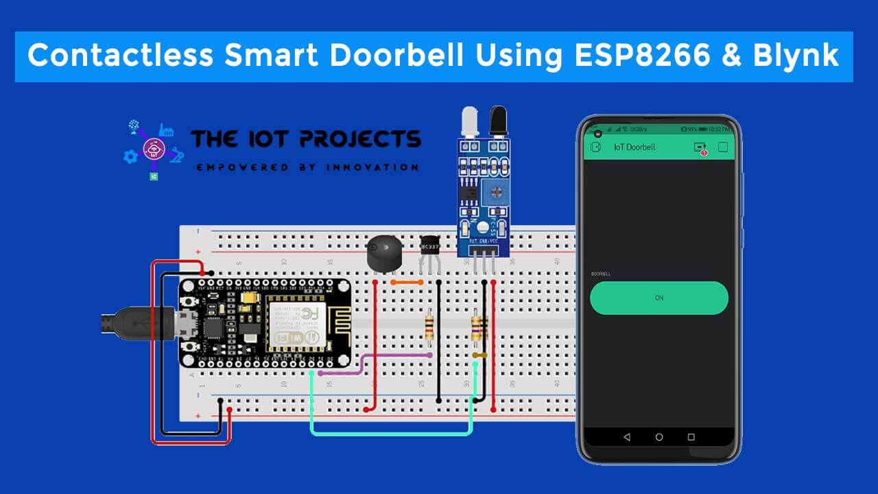
Considering the current Covid 19 “Corona Virus” situation, I decided to make a wireless smart IoT doorbell based on WiFi and IR sensors. You can call this project with different names like IoT based smart doorbell or Contactless smart doorbell using ESP8266.
Overview: Contactless Smart Doorbell using ESP8266
Doorbells are the foremost common germs infected objects in homes, hospitals, factories, and older homes. Our mission is to create a far better and healthier world, so we are building this project. This project will control and stop COVID-19 from spreading forward. Let’s work together to stop spreading the virus.
This smart wireless Contactless IoT doorbell is extremely user friendly based on WiFi and IR sensors. You’ll be able to make it yourself if you followed this tutorial. Before, getting started with circuit diagram and programming. I am going to describe how this project works.
When you are few kilometers far away from your home, you can take out your smartphone, open the app and press the button on your Android or iPhone, the buzzer set on the house notifies the household members. About your arrival and they open the door for you. In this way, you do not have to wait at the door for minutes.
Our Popular IoT Projects:
- IoT Based RFID Smart Door Lock System Using NodeMCU ESp8266
- IoT based Silent Intruder Alarm using Arduino
- Home Automation with MIT App Inventor and ESP8266
- Connect RFID to PHP & MySQL Database with NodeMcu ESP8266
- Home Automation with MIT App Inventor and ESP8266
- IoT Based RFID Attendance System using ESP32
- RFID Based Attendance System Using NodeMCU with PHP Web App
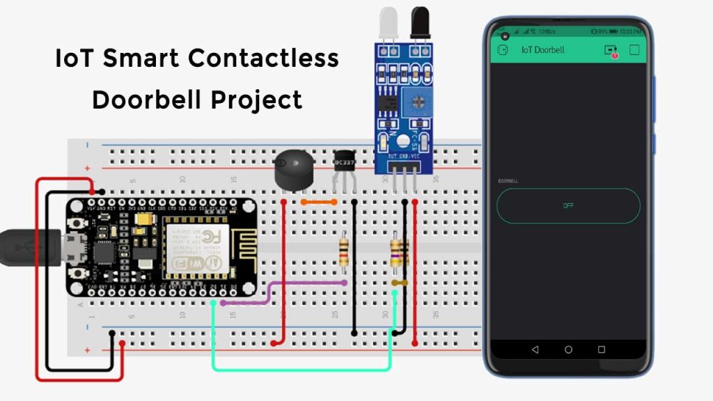
Further, the IR sensor is also interfaced with the Nodemcu ESP8266 module. The person near the door just shakes his/her hand in front of the IR sensor. At the same time, the buzzer is activated for a couple of seconds. Now the family members will get notice and open the door. Hence, there is no necessity of pressing any buttons. In this way, we can build a Contactless Smart doorbell using ESP8266 and Blynk IoT Application.
Topic covered this during this tutorial
- IoT based doorbell circuit diagram explanation
- Designing the IoT Doorbell mobile phone Application in Blynk
- Contactless Smart Doorbell Using ESP8266 Programming
Components required
The following are the list of the components required for making Contactless Smart Doorbell Using ESP8266.
- NodeMCU ESP8266 Development Board
- IR Sensor Module
- Buzzer
- Blynk IoT Application
NodeMCU ESP8266 Pinouts
The NodeMCU ESP8266 WiFi Module is an open-source Lua based firmware and development board. It is specifically targeted for IoT based applications. It includes firmware from the ESP8266 Wi-Fi SoC Espressif system and hardware based on the ESP-12 module.
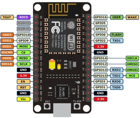
Most ESP8266 NodeMCU boards have an input voltage pin (Vin), three power pins (3.3v), four ground pins (GND), one analog pin (A0), and several digital pins (GPIO XX).
| Pin | Code | Arduino alias |
| A0 | A0 | A0 |
| D0 | GPIO 16 | 16 |
| D1 | GPIO 5 | 5 |
| D2 | GPIO 4 | 4 |
| D3 | GPIO 0 | 0 |
| D4 | GPIO 2 | 2 |
| D5 | GPIO 14 | 14 |
| D6 | GPIO 12 | 12 |
| D7 | GPIO 13 | 13 |
| D8 | GPIO 15 | 15 |
| SD2 | GPIO 9 | 9 |
| SD3 | GPIO 10 | 10 |
| RX | GPIO 3 | 3 |
| TX | GPIO 1 | 1 |
Specification & Features
- Microcontroller: Tensilica 32-bit RISC CPU Xtensa LX106
- Operating Voltage: 3.3V
- Input Voltage: 7-12V
- Digital I/O Pins (DIO): 16
- Analog Input Pins (ADC): 1
- UARTs: 1
- SPIs: 1
- I2Cs: 1
- Flash Memory: 4 MB
- SRAM: 64 KB
- Clock Speed: 80 MHz
- USB-TTL based on CP2102 is included onboard, Enabling Plug n Play
- PCB Antenna
- Small Sized module to fit smartly inside your IoT projects
Circuit Diagram: Contactless Smart Doorbell Using ESP8266 & Blynk
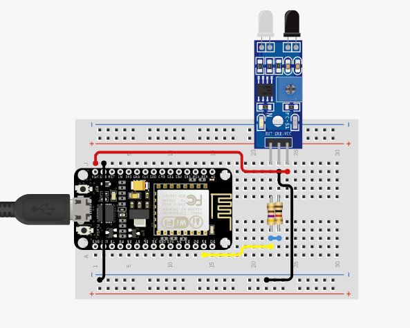
Interface all the components by looking at below circuit diagram and table for pin connection.
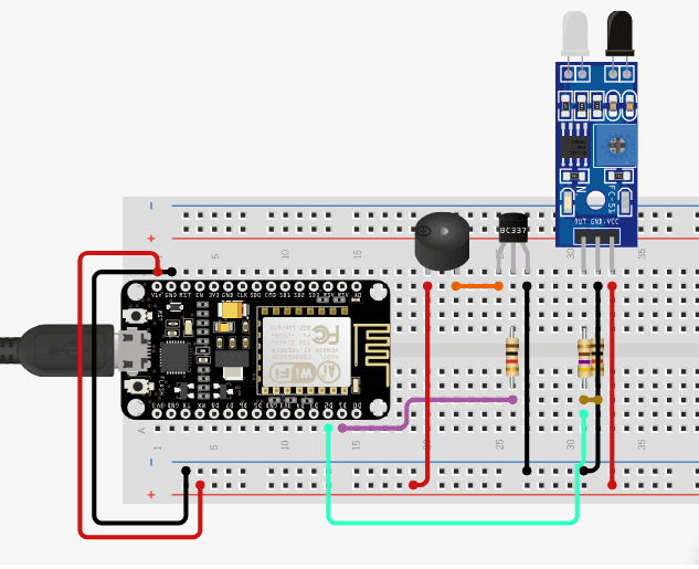
At first, we will interface IR Sensor with NodeMCU ESP8266 WiFi Module for IoT Doorbell Project.
| NodeMCU ESp8266 | IR Sensor |
| GND | GND |
| Vin | Vcc |
| D2 | Signal Pin through Resistor |
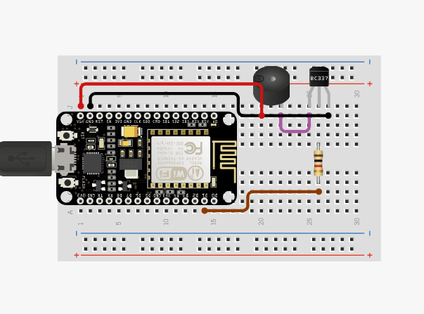
| Buzzer | NodeMCU ESP8266 |
| -ve | TSBC337 C |
| +ve | Vin |
| TSBC337 E | GND |
| Res1KO con0 | D1 |
IoT Doorbell App designed on Blynk
I have always been involved with the Blynk application and designed many apps before. In this session, I used some digital and virtual PIN for programming. Apart from this, my project has been tested to help you to check the code. Make sure you download and install the Blynk app from Playstore/Appstore.
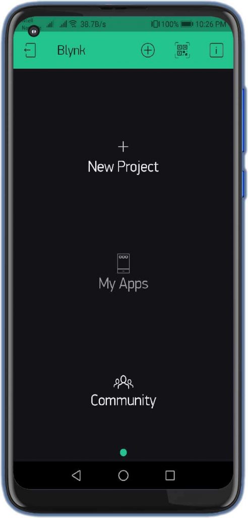
- First of all, open the blynk application.
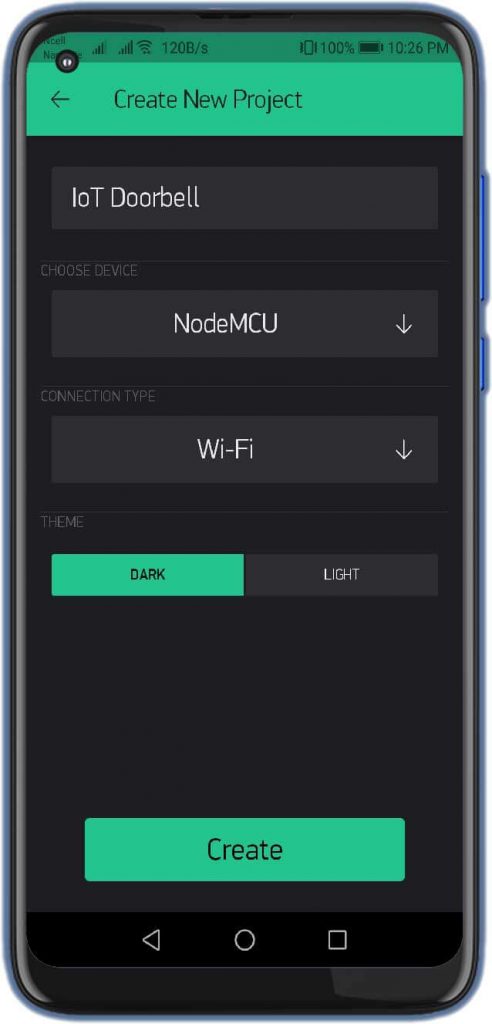
- Click on the create a new project and enter the project name as “IoT Doorbell“. Instead, you can type any name. You can change the name later.
- Click on Choice Tools and select NodeMCU ESP8266.
- Make sure the connection type is set to WIFI.
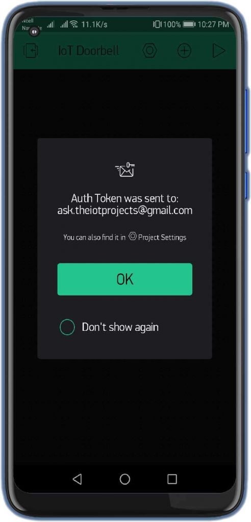
- Finally, click on the create button, a verification token will be sent to your email ID, which will be used in the Program CODE.
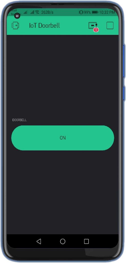
- Click anywhere on the screen, search for the button, and select the button. Now, click on the button to change the name or leave as it is. Click Output and select GP0/D2. Select the button mode as the switch and finally, you can change the font size. Now Your designed IoT doorbell application is ready to use.

Program Code Explanation
First of all, I started adding the libraries required for contactless smart doorbell using ESP8266. The download link is provided below.
#include <ESP8266WiFi.h>
#include <BlynkSimpleEsp8266.h>
#include <SimpleTimer.h>
#define BLYNK_PRINT Serial    // Comment this out to disable prints and save space
This is the authentication token which was sent via email while building the Blynk IoT App. This authentication token will be mailed to your registered email ID.
char auth[] = "Ay7TN0ucWH-aFJKX-h7cV07_as2omOHu";These are your WiFi router credentials, the SSDI and password. You can use mobile hotspot as well. In case you don’t have router.
/* WiFi credentials */
char ssid[] = "xxxxxxx";
char pass[] = "xxxxxxxx";
First of all the SimpleTimer variable is declared. Then the IR sensor and Buzzer Pins are defined. Inside the void setup() function, Serial Monitor and Blynk WiFi credentials are authenticated. PinMode Function for IR sensor and Buzzer is defined as INPUT and OUTPUT respectively.
SimpleTimer timer;
int IRsensor = D2; // IR Sensor Connected
int Buzzer = D1;

void setup()
{
  Serial.begin(115200);
  Blynk.begin(auth, ssid, pass);
  pinMode(IRsensor, INPUT_PULLUP);
  pinMode(D3, INPUT);
  pinMode(Buzzer, OUTPUT);

  timer.setInterval(1000L, Sensor);
  timer.setInterval(1000L, FromApp);
}
In the void loop() function, I am using only two functions which are timer.run() and Blynk.run() functions.
void loop()
{
  timer.run(); // Initiates SimpleTimer
  Blynk.run();
}
The void sensor () function is a user defined function, it has no return type and takes no argument as input. The purpose of this function is to check every second if there is anything in front of the IR sensor. If the IR sensor detects anything, it will open the buzzer for 2 seconds.
You’re probably wondering why I’m using Blynk. begin (auth, ssid, Pass); Avoid this again as I said earlier otherwise the NodeMCU module will be disconnected. I’m using a 2-second delay, so if NodeMCU module connectivity is disconnected with the Blynk application, it helps to reconnect again.
void Sensor()
{

while( digitalRead(IRsensor) == LOW)
{
  digitalWrite(Buzzer, HIGH);
  delay(2000); // Buzzer remains ON for 2 seconds.
  Blynk.begin(auth, ssid, pass); // this again connects the Blynk application.
}


}
The void FromApp () function is a user-defined function since it has no return type and does not take arguments as input. The purpose of this function is to check every second if a button is pressed on the Blynk application.
void FromApp()
{

 if(digitalRead(D3) == HIGH) // D3 is gp0 on the blynk app
 {
digitalWrite(Buzzer, HIGH);
 }
 if(digitalRead(D3) == LOW)
 {
digitalWrite(Buzzer, LOW);
 }

}
Source Code for Smart Doorbell
// IoT based Contactless Doorbell Project by
//https://iotprojectsideas.com/

/* Nodemcu ESP8266 & Blynk */
#include <ESP8266WiFi.h>
#include <BlynkSimpleEsp8266.h>
#include <SimpleTimer.h>

#define BLYNK_PRINT Serial    // Comment this out to disable prints and save space

char auth[] = "Ay7TN0ucWH-aFJKX-h7cV07_as2omOHu";
/* WiFi credentials */
char ssid[] = "xxxxxxx";
char pass[] = "xxxxxxxx";

SimpleTimer timer;
int IRsensor = D2; // IR Sensor Connected
int Buzzer = D1;

void setup()
{
  Serial.begin(115200);
  Blynk.begin(auth, ssid, pass);
  pinMode(IRsensor, INPUT_PULLUP);
  pinMode(D3, INPUT);
  pinMode(Buzzer, OUTPUT);

  timer.setInterval(1000L, Sensor);
  timer.setInterval(1000L, FromApp);
}

void loop()
{
  timer.run(); // Initiates SimpleTimer
  Blynk.run();
}

void Sensor()
{

while( digitalRead(IRsensor) == LOW)
{
  digitalWrite(Buzzer, HIGH);
  delay(2000); // Buzzer remains ON for 2 seconds.
  Blynk.begin(auth, ssid, pass); // this again connects the Blynk application.
}


}

void FromApp()
{

 if(digitalRead(D3) == HIGH) // D3 is gp0 on the blynk app
 {
digitalWrite(Buzzer, HIGH);
 }
 if(digitalRead(D3) == LOW)
 {
digitalWrite(Buzzer, LOW);
 }

}
Conclusion: IoT Doorbell using ESP8266
So that’s all about the Contactless Smart Doorbell Using ESP8266, IR Sensor, and a Buzzer. If you have any questions regarding this project, let me know in a comment below.


Code Not Working
Show error like this “Specific blynk template id and template name”
Is the code working now?
Please where can we get the step by step video on how to do this project