Getting Started With Stone HMI TFT LCD Display
Learn to Control WS2812 LED Strip with MCU board & Stone HMI Touch Display
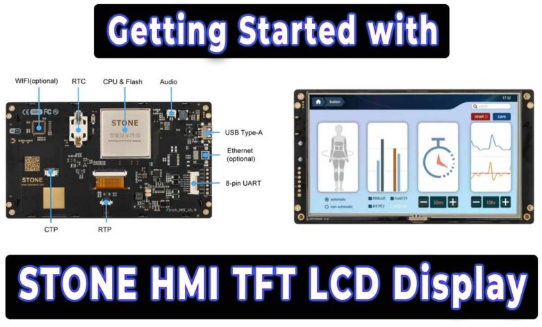
- Overview
- Components & Accessories from Stone
- Introduction to STWI070WT-01 Display
- Connect Display with PC
- Downloading Demo Project into Display
- Interfacing MCU board with Stone Display
- PCB Design, Gerber Files & PCB Ordering
- Software Setup
- Arduino Program Code
- DEMO: LED Strip Controller with Stone Display
- Conclusion
Overview
Are you looking to get into the world of Human Machine Interface (HMI) displays? If so, you’ve come to the right place! This comprehensive guide will take you through the exciting journey of Getting Started With Stone HMI TFT LCD Display. These Stone HMI displays offer a wide range of features and possibilities for your projects, whether you’re a hobbyist or a professional.
In this guide, we will cover everything from connecting the display to your computer to loading the program all in step-by-step. So, let’s start together and unlock the potential of the Stone HMI TFT LCD Display.
Components & Accessories from Stone
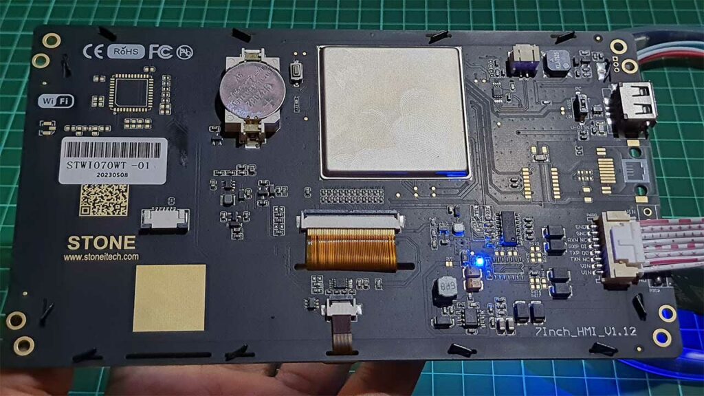
So, let’s start with the inbox materials. Here we get a 7-inch TFT LCD from Stone. The screen has a resolution of 800 by 480 pixels. It looks very neat from the front. While back looks a bit more complicated to understand. We will get into details about it later. We got a USB type-A male-to-male connector. This will be used for downloading the code to the display. Next, we have a UR2 RS232 PCB, which will be used for sending the UART commands to the display. It will also be used for supplying power to the display. The display can support a wide range of voltages, from 7V to 28V but 9V -12V is recommended.
| S.N | COMPONENTS NAME | QUANTITY | PURCHASE LINKS |
|---|---|---|---|
| 1 | Stone HMI Display (STWI070WT-01) | 1 | Amazon | AliExpress |
| 2 | WS2812 LED Strip | 1 | Amazon | AliExpress |
| 3 | Arduino Nano | 1 | Amazon | AliExpress |
| 4 | Type A USB Cable | 5 | Amazon | AliExpress |
Introduction to STWI070WT-01 Display
The STWI070WT-01 is a versatile Equipment TFT display and touch controller. It comes equipped with a processor, control program, TFT driver, flash memory, UART port, touch screen, and power supply. What sets it apart is its ability to supply Json Code & Hex Code instruction sets, making it compatible with any MCU for seamless control.
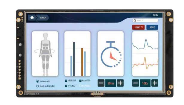
With the STWI070WT-01, you can perform various functions like Vector font display, image display, curve display, touch function, video, and audio playback. Its User Interface is rich and diverse, providing abundant options for customization. Additionally, the built-in flash memory allows you to store your data, configuration files, images, fonts, videos, and audio files for convenient access and management.
STWI070WT-01 Product Code
The STWI070WT-01 Display is a product code that holds vital information about the display’s specifications and features. Let’s decode the code step by step to gain a better understanding of its components.
- “ST” stands for the company code, indicating that this display is manufactured by the STONE Company whose initials are “ST.”
- The “W” in the code signifies that this version of the product is the third iteration.
- The “I” component denotes the display type. In this case, “I” indicates that it falls under the Industrial Type category. Alternatively, “A” would represent an Advanced Type, while “C” would represent a Civil Type.
- “070” in the code refers to the TFT Panel Dimension, meaning that the display is a 7-inch panel.
- “W” or “L” represents the operating voltage of the display. In this case, “W” indicates Wide Voltage, capable of operating in the range of +7V to +28V, while “L” would denote Low Voltage, operating within the +5V range.
- The “T” component reveals the presence of a touch screen on the display. Specifically, “T” means it is equipped with a Resistive Touch Screen, which offers precise touch input with pressure-sensitive technology. So it does not have multi-touch capability.
- The “0” signifies the interface type used for communication. In this case, “0” indicates RS232, while “4” would represent RS422/RS485, and “1” would signify TTL Level interface.
- The last component, “1,” is the hardware code, which might carry further details about the specific hardware configuration of the display.
- Lastly, the “E” in the code stands for Ethernet connectivity, while “W” would mean the display comes with WIFI capabilities, enabling it to connect to networks and access data remotely.
STWI070WT-01 Display Characteristics
- With Cortex A8 CPU/256MB Flash / TFT Driving device
- Controlled by any MCU via Json & Hex Code Instruction
- Display Image/Text / Curve / Video
- 262K (18bit) color TFT display
- With/without Touch Screen
- RS232/RS422/RS485/TTL UART Interface & USB port Downloading
- Ethernet port/WIFI Remote Control
- Wide voltage range/Strong Working Temperature
- Easy to use! Powerful function! Saving Much Development cost and time!
Application Area of Stone HMI Display
Widely used in various industrial fields
- Medical & Beauty Equipment
- Engineering Machinery and Vehicle Equipment
- Electronic Instrument
- Industrial Control System
- Electric Power Industry
- Civil Electronic Equipment
- Automation Equipment
- Traffic Field
- New energy project
- IoT applications etc.
Hardware Parts of Display
The hardware components of the display include:
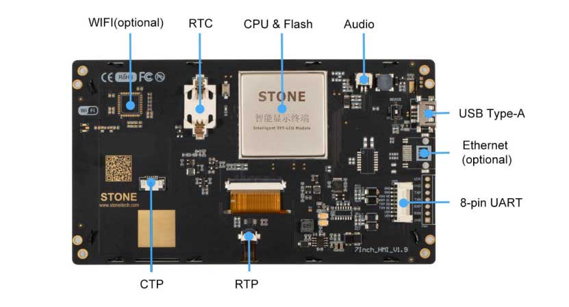
- Touch Screen: The touch-sensitive interface that allows users to interact with the display through touch inputs.
- TFT Panel: The Thin-Film Transistor panel, is responsible for displaying images and graphics with high resolution and color.
- CPU/Flash: The central processing unit and flash memory, which handle the processing and storage of data and program instructions for the display.
- USB Downloading Port: A USB port used for downloading firmware or software updates to the display.
- Ethernet Port (Optional): An optional Ethernet port that provides connectivity to networked systems for data transfer and remote access.
- 8-pin UART Port and Connector: A Universal Asynchronous Receiver-Transmitter port used for serial communication with other devices or microcontrollers.
- WiFi (Optional): An optional WiFi module that enables wireless communication and connectivity for the display.
- Audio Port for Adding Speaker: A port used for connecting an external speaker to provide audio output.
- Buzzer: A small sound-emitting component that can be used for audio notifications or alerts.
- RTC (Real-Time Clock): A clock circuit that keeps track of the current time and date, allowing the display to maintain accurate time-based functions.
These hardware parts work together to create a fully functional display that can handle touch inputs, display visuals, process data, communicate with other devices, and provide optional features like network connectivity, wireless communication, and audio capabilities.
Working Principle
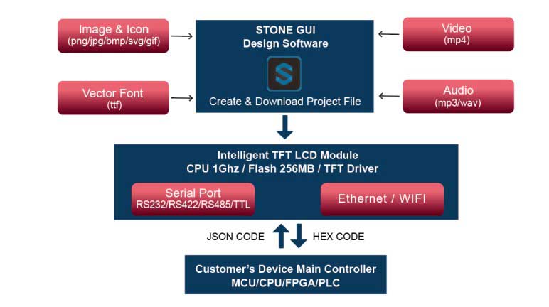
The Intelligent TFT-LCD Module communicates with the Customer’s MCU / CPU / FPGA / PLC via JSON Code and HEX Code Instructions. Then the MCU can control its connected equipment to work according to the received instructions.
Connect Display with PC
Now, for the connection, we will connect the cable to the USB to UART Module. You can also use a 12V DC adapter for powering up this display, but make sure the connection is set towards the port and not the USB.

I am using USB for this demo. This USB can be used to send the UART commands to the display. Therefore I am leaving the USB unconnected. Connect the cable to the display and make sure that the switch is set towards the device mode. Once we connect the adapter, the display will power on. You can also see a factory demo running on the display. At the back of the display, you can find the reset button to reset the screen.
Now Let’s move to the computer. You see here it gets detected as a mass storage device. But if you connect for the first time, it will show the driver error in the device manager. So you need to download these CH340 drivers. You can install the driver from here.
Alright, let’s download the user manual and software from stoneitech.com. Here you can read about their products. The products are sorted based on application or size. You can also go through the manual and datasheet for your device as well. Now let’s download the software for designing UI for the display.
After downloading the Stone Designer, install it and open it. Here we will simply load a demo project from the stone designer. We will further learn about this software and design our own UI in the next project.
Downloading Demo Project into Display
Simply, delete the old default folder and copy the default folder of the demo to the assets folder. It takes some time to copy.
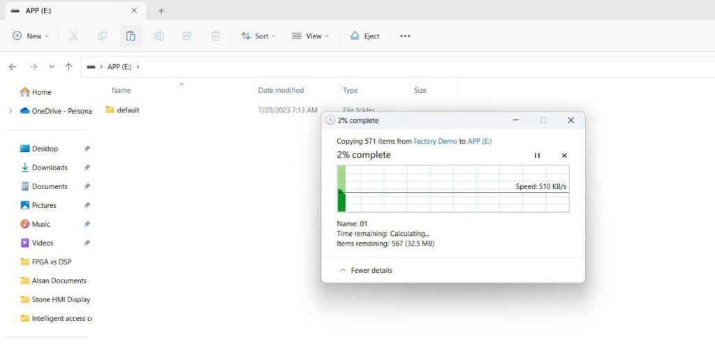
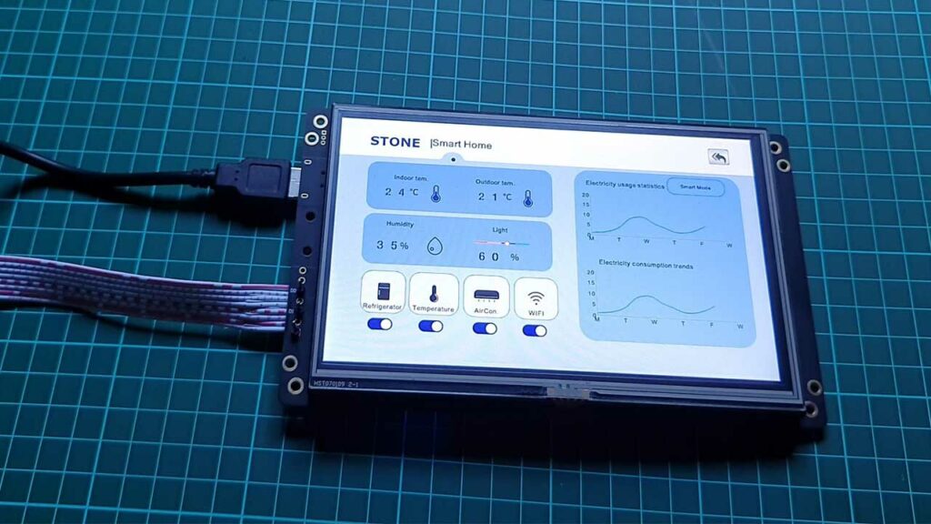
After a successful transfer, you can press the reset button on the back of the display. The new GUI will load. You can see the display working just as expected. The display is Touch Resistive so, you need to press hard sometime while exploring menus. Touch Resistive Panel does not support multi-touch. It is very useful in industrial applications.
Interfacing MCU board with Stone Display
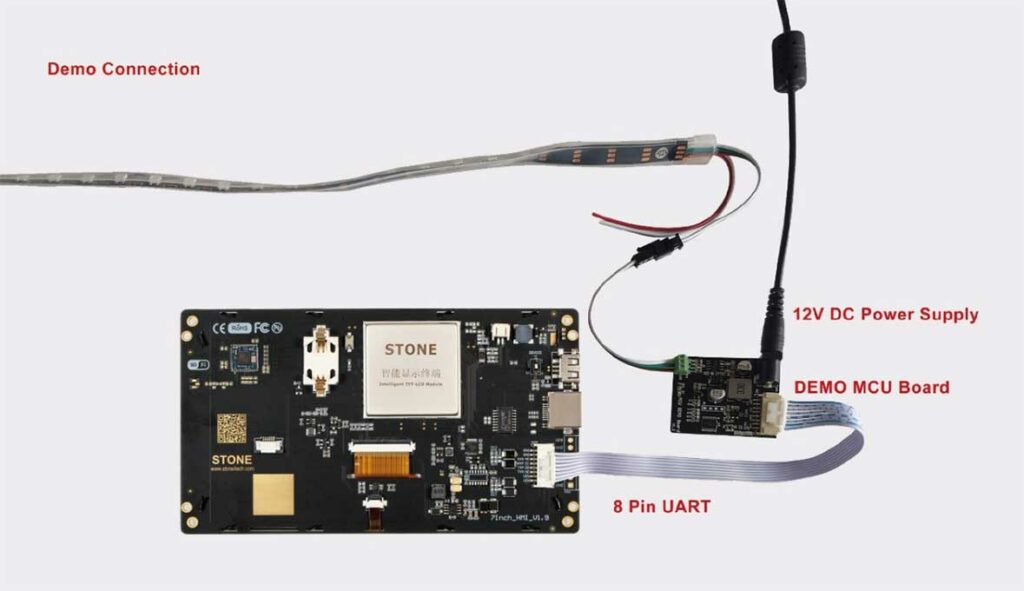
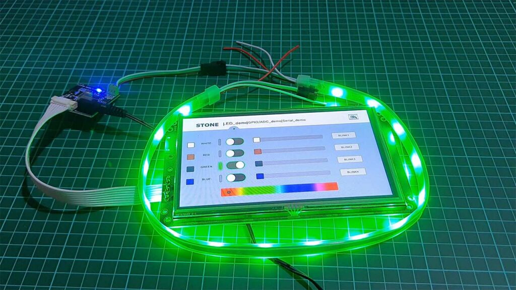
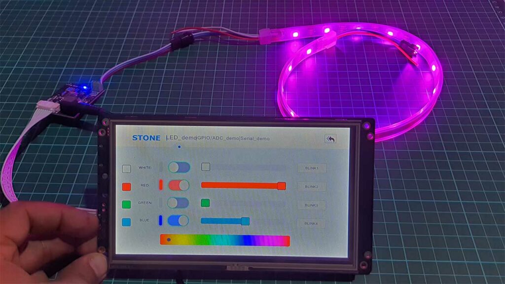
Now we will interface Stone STM32-based DEMO MCU Board to the Display and control WS2812 RGB LED Strip. First, we will attach 8 Pin UART connector one end to the MCU Demo board and the other end to the HMI Display. Attach the VCC, Data Input, and GND pins of the WS2812 LED Strip to the Respective pin on the MCU Board. Provide a 12V DC power supply to the DEMO MCU Board. Now we are all set. You can click on LED DEMO Menu on the LCD Main screen. For a better experience, you can use a stylus pen.
PCB Design, Gerber Files & PCB Ordering
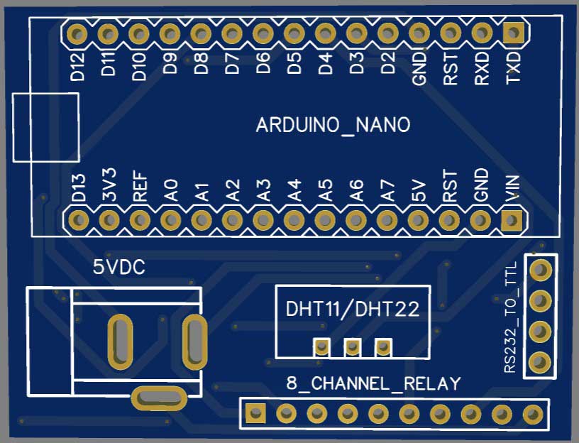
To assemble the components for testing, you can use a breadboard. However, for a more reliable and professional solution, I recommend using a custom PCB. I have already designed a custom PCB specifically for this project.
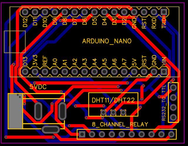
To access the Gerber file of the PCB, you can download it from the provided link.
Once you have the Gerber file, you can place an order for the PCB from PCBWay.com. Currently, PCBWay is celebrating their 10th Anniversary with amazing offers and special events! If you’re into electronics and PCB projects like me, you definitely don’t want to miss out on this.
PCBWay has been a trusted partner for PCB prototyping, manufacturing, and assembly for a decade now. To celebrate this milestone, they have a bunch of exciting deals and giveaways lined up. You can visit their special anniversary page at www.pcbway.com/activity/anniversary10th.html to participate.
I’ve been using PCBWay for my own projects, and their quality and customer service have always been top-notch. Whether you’re a hobbyist or a professional, PCBWay’s services are perfect for bringing your ideas to life.
And during this anniversary celebration, they are offering discounts, free trials, and even a chance to win some fantastic prizes!
So, what are you waiting for? Head over to PCBWay.com and join in the celebration. Let’s make some great projects together. Thanks again to PCBWay for sponsoring this project.
Software Setup
Arduino Program Code
You can also use an Arduino board instead of a DEMO MCU Board. The DEMO MCU board is preloaded with the program code. But in the Arduino board, you need to upload the following program code using Arduino IDE. Additionally, you will also need RS232 to TTL Converter module for serial communication with Display.
Install Required Libraries:
#include <StoneLCDLib.h>
#include <Adafruit_NeoPixel.h>

 /************************************************/
 /* stone_rgb_demo.ino                           */
 /*****************************************************************************/
 /*
  *  Controller demo that comes with Stone LCD Screens, but using the StoneLCD
  *  Arduino Library.
  *
  *
  * NOTE: THIS PROJECT REQUIRES THE ADAFRUIT NEOPIXEL LIBRARY.
  *  Install from the library manager.
  *
  * ***********************************************
  * Steps
  * ***********************************************
  * 1. Reduce the baud rate to 9600 in the included RGB Strip Demo Project.
  * 2. Replace the STM32 with an Arduino Uno/Nano/Pro Mini/ etc
  *
  *  ARDUINO      MODULE                PIN
  *  -----------------------------------------------
  *  0 (RX)       TTL-RS232 Converter   RX <-
  *  1 (TX)       TTL-RS232 Converter   TX ->
  *  9            RGB Strip             DI
  *
  *  (Check "pin assignment" section to change).
  */

/*############################################################################
 *##                                                                        ##
 *##                               D E F I N E S                            ##
 *##                                                                        ##
 *############################################################################*/
 /* Pin assignment *******************************/
#define LED_PIN               9

 /* Buttons and Labels IDs ***********************/
#define BTTN_ONOFF            0x0001
#define ICON_WHITE            0x0002
#define ICON_RED              0x0003
#define ICON_GREEN            0x0004
#define ICON_BLUE             0x0005

#define TEXT_WHITE            0x0006
#define TEXT_RED              0x0007
#define TEXT_GREEN            0x0008
#define TEXT_BLUE             0x0009

#define BTTN_BLINK1           0x000A
#define BTTN_BLINK2           0x000B
#define BTTN_BLINK3           0x000C
#define BTTN_BLINK4           0x000D
#define NUM_OF_LEDS           0x0033

#define ICON_OFF              0
#define ICON_ON               1

/* Other constants ******************************/
#define MAX_RECV_BUFFER       4
#define MAX_LED_COUNT         27

/*############################################################################
 *##                                                                        ##
 *##                                G L O B A L                             ##
 *##                                                                        ##
 *############################################################################*/
struct {
  byte white;
  byte red;
  byte green;
  byte blue;
}rgbStatus;

StoneLCD          myLCD (&Serial);  // Can use a soft-serial port if care is taken
                                    //  to constantly scan for incoming messages.
Adafruit_NeoPixel strip(MAX_LED_COUNT, LED_PIN, NEO_GRB + NEO_KHZ800);

StoneLCDEvent evt;
uint16_t      recvBuffer[MAX_RECV_BUFFER];
uint8_t       led_count = MAX_LED_COUNT;

// The following variables are used by the blinking functions, which were copied
// directly from the example provided by STONE.
uint8_t       blink_type = 0;
uint8_t       times = 0;
uint8_t       BLINK_2 = 0;
uint8_t       USER_R = 0, USER_G = 0, USER_B = 0, COLOR_TYPE = 0, COLOR_DIR = 0;
uint16_t      k, q;

/*############################################################################
 *##                                                                        ##
 *##                      U I   H A N D L I N G                             ##
 *##                                                                        ##
 *############################################################################*/
void updateWRGBIcons(){
  myLCD.writeVariableWord(ICON_WHITE,   (rgbStatus.white > 0));
  myLCD.writeVariableWord(ICON_RED,     (rgbStatus.red > 0));
  myLCD.writeVariableWord(ICON_GREEN,   (rgbStatus.green > 0));
  myLCD.writeVariableWord(ICON_BLUE,    (rgbStatus.blue > 0));
}

void updateUIFromrgbStatus(){
  myLCD.writeVariableWord(TEXT_WHITE,   rgbStatus.white);
  myLCD.writeVariableWord(TEXT_RED,     rgbStatus.red);
  myLCD.writeVariableWord(TEXT_GREEN,   rgbStatus.green);
  myLCD.writeVariableWord(TEXT_BLUE,    rgbStatus.blue);

  updateWRGBIcons();
}

void updatergbStatusFromUI() {
  rgbStatus.white     = myLCD.readVariableWord(TEXT_WHITE);
  rgbStatus.red       = myLCD.readVariableWord(TEXT_RED);
  rgbStatus.green     = myLCD.readVariableWord(TEXT_GREEN);
  rgbStatus.blue      = myLCD.readVariableWord(TEXT_BLUE);
}

void checkForSwitchAutoOff(){
  if ((rgbStatus.red == 0) && (rgbStatus.green == 0) && (rgbStatus.blue == 0) && (rgbStatus.white == 0) && (blink_type == 0)){
    myLCD.writeVariableWord(BTTN_ONOFF, ICON_OFF);
  }else{
    myLCD.writeVariableWord(BTTN_ONOFF, ICON_ON);
  }
}
/*############################################################################
 *##                                                                        ##
 *##                          R G B   S T R I P                             ##
 *##                                                                        ##
 *############################################################################*/
void setFullRGBStrip(byte r, byte g, byte b){
  byte i;
  for (i=0; i < led_count; i++) strip.setPixelColor(i, r, g, b);
  for (i=led_count; i < MAX_LED_COUNT; i++) strip.setPixelColor(i, 0, 0, 0);
  strip.show();
}

void updateRGBStrip(){
  byte r, g, b;

  if (rgbStatus.white == 0){
    r = rgbStatus.red;
    g = rgbStatus.green;
    b = rgbStatus.blue;
  }else{
    r = rgbStatus.white;
    g = rgbStatus.white;
    b = rgbStatus.white;
  }
  setFullRGBStrip(r, g, b);
}

/*############################################################################
 *##                                                                        ##
 *##                       C O N T R O L   L O G I C                        ##
 *##                                                                        ##
 *############################################################################*/
 void allRGBOff(){
  rgbStatus.white = 0;
  rgbStatus.red   = 0;
  rgbStatus.green = 0;
  rgbStatus.blue  = 0;
}

void blink1(){
  times++;
  if (times >= 14) {
    times = 0;
    if (COLOR_DIR == 0) {
      if (COLOR_TYPE == 0) {
        USER_R++;
        USER_G = 0;
        USER_B = 0;
      } else if (COLOR_TYPE == 1) {
        USER_R = 0;
        USER_G++;
        USER_B = 0;
      } else if (COLOR_TYPE == 2) {
        USER_R = 0;
        USER_G = 0;
        USER_B++;
      } else if (COLOR_TYPE == 3) {
        USER_R++;
        USER_G++;
        USER_B = 0;
      } else if (COLOR_TYPE == 4) {
        USER_R = 0;
        USER_G++;
        USER_B++;
      } else if (COLOR_TYPE == 5) {
        USER_R++;
        USER_G = 0;
        USER_B++;
      }
      if ((USER_R >= 250) || (USER_G >= 250) || (USER_B >= 250)) {
        COLOR_DIR = 1;
      }
    } else {
      if (COLOR_TYPE == 0) {
        USER_R--;
        USER_G = 0;
        USER_B = 0;
      } else if (COLOR_TYPE == 1) {
        USER_R = 0;
        USER_G--;
        USER_B = 0;
      } else if (COLOR_TYPE == 2) {
        USER_R = 0;
        USER_G = 0;
        USER_B--;
      } else if (COLOR_TYPE == 3) {
        USER_R--;
        USER_G--;
        USER_B = 0;
      } else if (COLOR_TYPE == 4) {
        USER_R = 0;
        USER_G--;
        USER_B--;
      } else if (COLOR_TYPE == 5) {
        USER_R--;
        USER_G = 0;
        USER_B--;
      }
      if ((USER_R == 0x02) || (USER_G == 0x02) || (USER_B == 0x02)) {
        COLOR_DIR = 0;
        COLOR_TYPE++;
        if (COLOR_TYPE > 5) COLOR_TYPE = 0;
      }
    }
    setFullRGBStrip (USER_R, USER_G, USER_B);
  }
  delay(1);
}

void blink2(){
  k++;
  if (k >= 150){
    k = 0;
    q = 200;

    BLINK_2++;
    if (BLINK_2 > 8) BLINK_2 = 0;

    if (BLINK_2 == 0)       setFullRGBStrip(q, 0, 0);
    else if (BLINK_2 == 1)  setFullRGBStrip(0, q, 0);
    else if (BLINK_2 == 2)  setFullRGBStrip(0, 0, q);
    else if (BLINK_2 == 3)  setFullRGBStrip(q, q, 0);
    else if (BLINK_2 == 4)  setFullRGBStrip(0, q, q);
    else if (BLINK_2 == 5)  setFullRGBStrip(q, 0, q);
    else if (BLINK_2 == 6)  setFullRGBStrip(q - 100, q, 0);
    else if (BLINK_2 == 7)  setFullRGBStrip(0, q - 80, q);
    else if (BLINK_2 == 8)  setFullRGBStrip(q, 0, q - 120);
  }
  delay(1);
}

void blink3(){
  k++;
  if (k >= 1000) {
    k = 0;

    BLINK_2++;
    if (BLINK_2 > 5) BLINK_2 = 0;

    if (BLINK_2 == 0)      setFullRGBStrip(q, 0, 0);
    else if (BLINK_2 == 1) setFullRGBStrip(0, q, 0);
    else if (BLINK_2 == 2) setFullRGBStrip(0, 0, q);
    else if (BLINK_2 == 3) setFullRGBStrip(q, q, 0);
    else if (BLINK_2 == 4) setFullRGBStrip(0, q, q);
    else if (BLINK_2 == 5) setFullRGBStrip(q, 0, q);
  }
  delay(1);
}

void blink4(){
  k++;
  if (k >= 500) {
    k = 0;
    q = 0;
    BLINK_2++;
    if (BLINK_2 > 5) BLINK_2 = 0;
  }
  q++;
  if (q >= 250) q = 0;

  if (BLINK_2 == 0)      setFullRGBStrip(q, 0, 0);
  else if (BLINK_2 == 1) setFullRGBStrip(0, q, 0);
  else if (BLINK_2 == 2) setFullRGBStrip(0, 0, q);
  else if (BLINK_2 == 3) setFullRGBStrip(q, q, 0);
  else if (BLINK_2 == 4) setFullRGBStrip(0, q, q);
  else if (BLINK_2 == 5) setFullRGBStrip(q, 0, q);
  delay(1);
}

/*############################################################################
 *##                                                                        ##
 *##                    M I S C    F U N C T I O N S                        ##
 *##                                                                        ##
 *############################################################################*/
void setDateTime(){
  StoneLCDDateTime dateTime(2020, 12, 31, 0, 23, 59, 58);
  myLCD.setRTC(&dateTime);
}

/*############################################################################
 *##                                                                        ##
 *##                                 S E T U P                              ##
 *##                                                                        ##
 *############################################################################*/
void setup() {
  // *** Initialize RGB strip
  strip.begin();

  // *** Initialize serial port
  Serial.begin(9600);
  while (!Serial) {
    ; // wait for serial port to connect. Needed for native USB port only
  }

  // *** Wait a bit before starting, and then set the time,
  delay(1000);
  // Comment the following line if you don't want the time/date of your
  // LCD to be overwritten
  setDateTime();

  // Read UI values into our app data
  updatergbStatusFromUI();

  // Also read initial LED count
  led_count = myLCD.readVariableWord(NUM_OF_LEDS);

  // Let's start the loop() cycle discarding pending bytes from the screen,
  // if any.
  myLCD.clearInputStream();
}

/*############################################################################
 *##                                                                        ##
 *##                                  L O O P                               ##
 *##                                                                        ##
 *############################################################################*/
void loop() {
  byte i;
  byte value;
  boolean recvEvent;

  recvEvent = myLCD.checkForIOEvent(&evt, recvBuffer, MAX_RECV_BUFFER);
  if (recvEvent){
    // Let's clear any remaining of pending messages
    myLCD.clearInputStream();

    // All values the UI handles for this example are bytes, so let's get the
    // first byte in the message content, and use it as the value from now on
    value = recvBuffer[0];

    switch (evt.address){
      case NUM_OF_LEDS:
        led_count = value;
        updateRGBStrip();
        break;

      case BTTN_ONOFF:
        blink_type = 0;
        if (value == 0){
          allRGBOff();
        } else {
          rgbStatus.white = 0;
          rgbStatus.red   = 0x24;
          rgbStatus.green = 0x10;
          rgbStatus.blue  = 0x32;
        }
        updateRGBStrip();
        break;

      case TEXT_WHITE:
        allRGBOff();
        blink_type      = 0;
        rgbStatus.white = value;
        updateRGBStrip();
        break;

      case TEXT_RED:
        blink_type      = 0;
        rgbStatus.red   = value;
        rgbStatus.white = 0;
        updateRGBStrip();
        break;

      case TEXT_GREEN:
        blink_type      = 0;
        rgbStatus.green = value;
        rgbStatus.white = 0;
        updateRGBStrip();
        break;

      case TEXT_BLUE:
        blink_type      = 0;
        rgbStatus.blue  = value;
        rgbStatus.white = 0;
        updateRGBStrip();
        break;

      case BTTN_BLINK1:
        blink_type = 1;
        allRGBOff();
        break;

      case BTTN_BLINK2:
        blink_type = 2;
        allRGBOff();
        break;

      case BTTN_BLINK3:
        blink_type = 3;
        allRGBOff();
        break;

      case BTTN_BLINK4:
        blink_type = 4;
        allRGBOff();
        break;
    }
    checkForSwitchAutoOff();
    updateUIFromrgbStatus();
  } else {
    // No event received from the UI,
    // process / animate current blinking seq.
    if (blink_type == 1)      blink1();
    else if (blink_type == 2) blink2();
    else if (blink_type == 3) blink3();
    else if (blink_type == 4) blink4();
  }
}
DEMO: LED Strip Controller with Stone Display
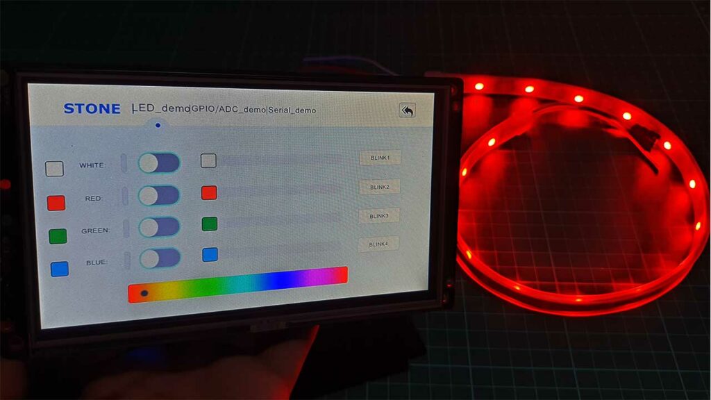
After completing circuit assembly and uploading program code you can test this demo project. Provide the 12V DC power supply to the MCU board and you can control the LED Strip through buttons on LCD. You can also control brightness and color contrast using this simple DEMO GUI.
Conclusion
In conclusion, we have explored the various aspects of the display, from its hardware components to its functionalities. We successfully connected the display to a PC, enabling us to upload and run a demo program effortlessly. Moreover, we took it a step further by controlling an RGB LED strip with the help of a demo MCU board and the display, showcasing its versatility and compatibility with different devices.
Looking ahead to our next project, we are excited to take full advantage of the Stone Designer software and create our own Graphical User Interface (GUI). We can’t wait to see the amazing projects that will come to life with the Stone HMI TFT LCD Display.
Check our Previous tutorials based on HMI Displays:

