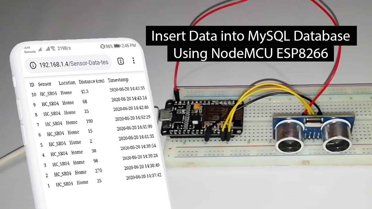
In this tutorial, I am going to show how we can insert sensor data into the MySQL database using ESP8266. we will also design a webpage that displays the sensor readings, with timestamps and other information from the database. You can visualize sensor data from anywhere by accessing the server.
For demonstration purposes, we’ll be using an Ultrasonic HC-SR04 sensor connected to an ESP8266 board. You can modify the program code to send readings from a different sensor like DHT11/DHT22, BMP180/BMP280, etc. or use multiple boards.
Components Required
In order to Insert Data into MySQL Database with ESP8266 Development Board, you’ll use these components:
Hardware components:
- NodeMCU ESP8266 Development Board
- Ultrasonic HC-SR04 Sensor
- Few jumper wires
Software Components:
- Hosting server and domain name/ Xampp Server
- PHP script to insert data into MySQL database and display it on a web page
- MySQL database to store sensor readings
PHP Script to Insert Data into MySQL Database
Here, we’re going to create a PHP script that is responsible for receiving incoming data from NodeMCU ESP8266 and insert data into a MySQL database.
Now start the Apache and MySQL server from the xampp control panel. Then go to the xampp htdocs folder and create a new folder called “Sensor-data-test“.
For Demonstration, we are using the xampp server. If you are using any Hosting service then you need to go to Cpanel and under public_html folder create a new file called “sensor-data.php“.
First, we will create a file called sensor-data.php. The main purpose of this file is to establish a connection between the website script and the MySQL database. Below this is the code for “sensor-data.php” where the host configuration, dbname, user, etc. can be changed according to your respective database configuration.
<!DOCTYPE html>
<html>
<body>
<?php
/*
  Alsan Parajuli
  Complete project details at https://iotprojectsideas.com/

  Permission is hereby granted, free of charge, to any person obtaining a copy
  of this software and associated documentation files.

  The above copyright notice and this permission notice shall be included in all
  copies or substantial portions of the Software.
*/
$servername = "localhost";
// REPLACE with your Database name
$dbname = "sensor database";
// REPLACE with Database user
$username = "iot projects";
// REPLACE with Database user password
$password = "admin@TheIoTProjects.com";
// Create connection
$conn = new mysqli($servername, $username, $password, $dbname);
// Check connection
if ($conn->connect_error) {
die("Connection failed: " . $conn->connect_error);
}
strtotime("$row_reading_time + 4 hours"));
$conn->close();
?>
</table>
</body>
</html>The above code has two major functions. First, $conn will start the database connection, and conn->close; closes the database connection.
Second, this sensor-data.php file will initiate GET requests to display the data that has been recorded in the database in tabular form.
$sql = "SELECT id, sensor, location, distance, reading_time FROM SensorData ORDER BY id DESC";

echo '<table cellspacing="5" cellpadding="5">
      <tr>
        <td>ID</td>
        <td>Sensor</td>
        <td>Location</td>
        <td>Distance (cm)</td>
        <td>Timestamp</td>
      </tr>';

if ($result = $conn->query($sql)) {
    while ($row = $result->fetch_assoc()) {
        $row_id = $row["id"];
        $row_sensor = $row["sensor"];
        $row_location = $row["location"];
        $row_distance = $row["distance"];
        $row_reading_time = $row["reading_time"];
 echo '<tr>
                <td>' . $row_id . '</td>
                <td>' . $row_sensor . '</td>
                <td>' . $row_location . '</td>
                <td>' . $row_distance . '</td>
                <td>' . $row_reading_time . '</td>
              </tr>';
    }
    $result->free();
}
In the sensor-data.php file, the $conn function will be called and execute a SELECT query to get data from the database and form a table containing the data before closing the database connection.
Third, we will create a file called post-sensor-data.php which will handle POST requests where this script will be the gateway for recording data to the MySQL database. Below is the contents of this file.
<?php

/*
  Alsan Parajuli
  Complete project details at https://iotprojectsideas.com/

  Permission is hereby granted, free of charge, to any person obtaining a copy
  of this software and associated documentation files.

  The above copyright notice and this permission notice shall be included in all
  copies or substantial portions of the Software.
*/

$servername = "localhost";

// REPLACE with your Database name
$dbname = "sensor database";
// REPLACE with Database user
$username = "iot projects";
// REPLACE with Database user password
$password = "admin@TheIoTProjects.com";

// Keep this API Key value to be compatible with the ESP8266 code provided in the project page.
// If you change this value, the ESP8266 sketch needs to match
$api_key_value = "tPmAT5Ab3j7F9";

$api_key= $sensor = $location = $value1 = $value2 = $distance = "";
if ($_SERVER["REQUEST_METHOD"] == "POST") {
    //$api_key = test_input($_POST["api_key"]);
    if($api_key == $api_key_value) {
        $sensor = test_input($_POST["sensor"]);
        $location = test_input($_POST["location"]);
        $distance = test_input($_POST["distance"]);

        // Create connection
        $conn = new mysqli($servername, $username, $password, $dbname);
        // Check connection
        if ($conn->connect_error) {
            die("Connection failed: " . $conn->connect_error);
        }

        $sql = "INSERT INTO sensordata (sensor, location, distance)
        VALUES ('" . $sensor . "', '" . $location . "', '" . $distance . "')";

        if ($conn->query($sql) === TRUE) {
            echo "New record created successfully";
        }
        else {
            echo "Error: " . $sql . "<br>" . $conn->error;
        }

        $conn->close();
    }
    else {
        echo "Wrong API Key provided.";
    }

}
else {
    echo "No data posted with HTTP POST.";
}

function test_input($data) {
    $data = trim($data);
    $data = stripslashes($data);
    $data = htmlspecialchars($data);
    return $data;
}
In this script, database connection initiation, API Key validation, and request method will be performed. In the API Key, you can put any random numbers. Here, I set $api_key_value = “tPmAT5Ab3j7F9“. After that, the data will be executed in a query and entered into the database. If something went wrong (like wrong API Key, incomplete input data, or wrong method), the query will be canceled.
Testing the PHP MySQL Database and a Web Page
Now Go To PhpMyAdmin and create a New Database “sensor database“. Then, go to privilege and create a new user, for example username = “iot projects“, host=”localhost“, password = “admin@TheIoTProjects.com“. Finally, Go to SQL Section and Paste the following script and click on Go.
CREATE TABLE SensorData (
    id INT(6) UNSIGNED AUTO_INCREMENT PRIMARY KEY,
    sensor VARCHAR(30) NOT NULL,
    location VARCHAR(30) NOT NULL,
    distance VARCHAR(10),
    reading_time TIMESTAMP DEFAULT CURRENT_TIMESTAMP ON UPDATE CURRENT_TIMESTAMP
)
To test the PHP server, You can use the POSTMAN application with data bodies that are needed according to your projects. For this project, we need API Key, Sensor, Location, and Distance.
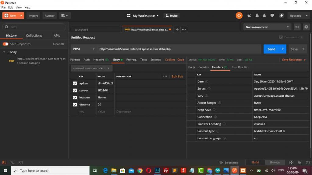
When I checked the data provided is successfully recorded in the database
Setting Up NodeMCU ESp8266 to Insert Data into MySQL Database
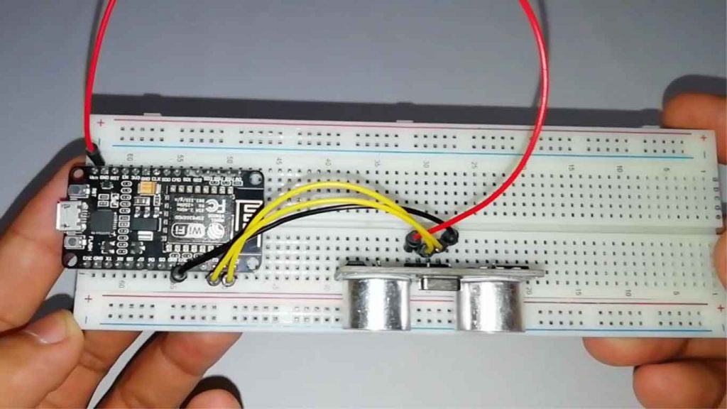
The HC-SR04 Ultrasonic sensor module provides the measurement of the time that it takes for sound to bounce off an object and return back to the sensor. Want to know more visit the Link- Working Principle of HC-SR04 Ultrasonic Sensor. Following are the wiring details for connecting the ESP8266 Development Board to the HC-SR04 sensor:
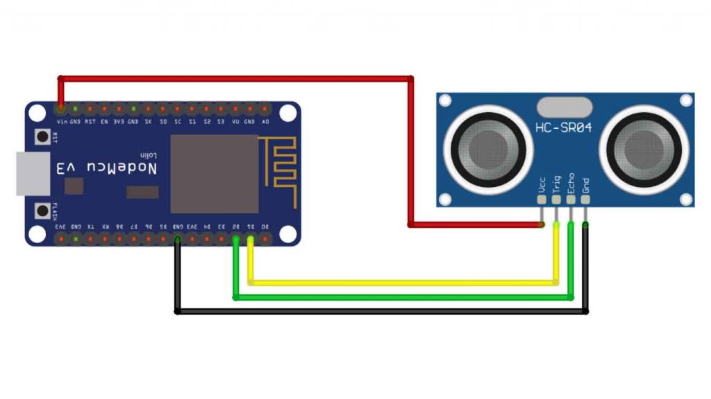
Ultrasonic HC-SR04 wiring to ESP8266
| Ultrasonic HC-SR04 | ESP8266 |
| Vcc Pin | Vin Pin |
| Trig Pin | D1 (GPIO 5) |
| Echo Pin | D2 (GPIO 4) |
| GND Pin | GND |
Program Code Explanation
We’ll program the ESP8266 board using Arduino IDE, so you must have the following library file installed in your Arduino IDE. You can Download them from library manager on Arduino IDE.
#include <ESP8266WiFi.h>
#include <ESP8266HTTPClient.h>
#include <WiFiClient.h>
#include <Wire.h>
#include <Ultrasonic.h>
// Instantiate trig and echo pin for ultrasonic sensor
Ultrasonic ultrasonic(5, 4);
const char* ssid     = "Alsan Air WiFi 4";
const char* password = "11122235122@kap";
const char* serverName = "http://192.168.1.4/Sensor-data-test/post-sensor-data.php";
// Example: http://xxx/post-sensor-data.php";
String apiKeyValue = "theiotprojects";
// Example: tPmAT5Ab3j7F9
String sensorName = "HC-SR04";
String sensorLocation = "Home";
The above program indicates that we are importing the library modules needed for this program. Then we also need to instantiate sensors on the trig and echo pins, and we need to define variables that will be used in this program such as SSID and network passwords, server addresses (API endpoints), API Key, sensor names, and location for reading data.
void setup() {
  Serial.begin(115200);

  WiFi.begin(ssid, password);
  Serial.println("Connecting");
  while (WiFi.status() != WL_CONNECTED) {
    delay(500);
    Serial.print(".");
  }
  Serial.println("");
  Serial.print("Connected to WiFi network with IP Address: ");
  Serial.println(WiFi.localIP());
}
In the setup procedure above, the WiFi network will be initialized and display the usable IP address.
void loop() {
  if (WiFi.status() == WL_CONNECTED) {
    HTTPClient http;
    http.begin(serverName);

    http.addHeader("Content-Type", "application/x-www-form-urlencoded");

    // Prepare your HTTP POST request data
    String httpRequestData = "api_key=" + apiKeyValue + "&sensor=" + sensorName + "&location=" + sensorLocation + "&distance=" + String(ultrasonic.read()) + "";
    //String httpRequestData = "api_key=theiotprojects&sensor=HC-SR04&location=Home&distance=24.75";
    Serial.print("httpRequestData: ");
    Serial.println(httpRequestData);
    // Send HTTP POST request
    int httpResponseCode = http.POST(httpRequestData);

    if (httpResponseCode > 0) {
      Serial.print("HTTP Response code: ");
      Serial.println(httpResponseCode);
    }
    else {
      Serial.print("Error code: ");
      Serial.println(httpResponseCode);
    }
    // Free resources
    http.end();
  }
  else {
    Serial.println("WiFi Disconnected");
  }
  //Send an HTTP POST request every 20 seconds
  delay(10000);
}
In the above loop procedure, a request will be made using the POST method to the PHP server that we have prepared previously.
String httpRequestData = "api_key=" + apiKeyValue + "&sensor=" + sensorName + "&location=" + sensorLocation + "&distance=" + String(ultrasonic.read()) + "";The above code is a Query String that will be passed to the server to be recorded in the database.
int httpResponseCode = http.POST(httpRequestData);Then, the code above is a method for making a request to the server that has been started ( http.begin (serverName) ). If this is successful, the data will be recorded in the MySQL database.
Program Code for Inserting Data to MySQL Database with ESP8266
This is a program source code for Inserting Data into MySQL Database with ESP8266 Development Board. Simply, copy the program code and compile it using the Arduino IDE to program the ESP8266 Development Board and HC-SR04 sensor.
#include <ESP8266WiFi.h>
#include <ESP8266HTTPClient.h>
#include <WiFiClient.h>
#include <Wire.h>
#include <Ultrasonic.h>
// Instantiate trig and echo pin for ultrasonic sensor
Ultrasonic ultrasonic(5, 4);
const char* ssid     = "Alsan Air WiFi 4";
const char* password = "11122235122@kap";
const char* serverName = "http://192.168.1.4/Sensor-data-test/post-sensor-data.php";
// Example: http://xxx.com/esp_hcsr04_php_post.php
String apiKeyValue = "theiotprojects";
// Example: tPmAT5Ab3j7F9
String sensorName = "HC-SR04";
String sensorLocation = "Home";
void setup() {
  Serial.begin(115200);

  WiFi.begin(ssid, password);
  Serial.println("Connecting");
  while (WiFi.status() != WL_CONNECTED) {
    delay(500);
    Serial.print(".");
  }
  Serial.println("");
  Serial.print("Connected to WiFi network with IP Address: ");
  Serial.println(WiFi.localIP());
}
void loop() {
  if (WiFi.status() == WL_CONNECTED) {
    HTTPClient http;
    http.begin(serverName);

    http.addHeader("Content-Type", "application/x-www-form-urlencoded");

    // Prepare your HTTP POST request data
    String httpRequestData = "api_key=" + apiKeyValue + "&sensor=" + sensorName + "&location=" + sensorLocation + "&distance=" + String(ultrasonic.read()) + "";
    //String httpRequestData = "api_key=theiotprojects&sensor=HC-SR04&location=Home&distance=24.75";
    Serial.print("httpRequestData: ");
    Serial.println(httpRequestData);
    // Send HTTP POST request
    int httpResponseCode = http.POST(httpRequestData);

    if (httpResponseCode > 0) {
      Serial.print("HTTP Response code: ");
      Serial.println(httpResponseCode);
    }
    else {
      Serial.print("Error code: ");
      Serial.println(httpResponseCode);
    }
    // Free resources
    http.end();
  }
  else {
    Serial.println("WiFi Disconnected");
  }
  //Send an HTTP POST request every 20 seconds
  delay(10000);
}
Upload the Code
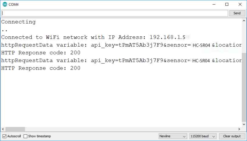
Then the last one is that we have to upload the program code to the ESP8266 board by clicking on the arrow in the top left corner. After uploading, open the serial monitor to see the status of the project.
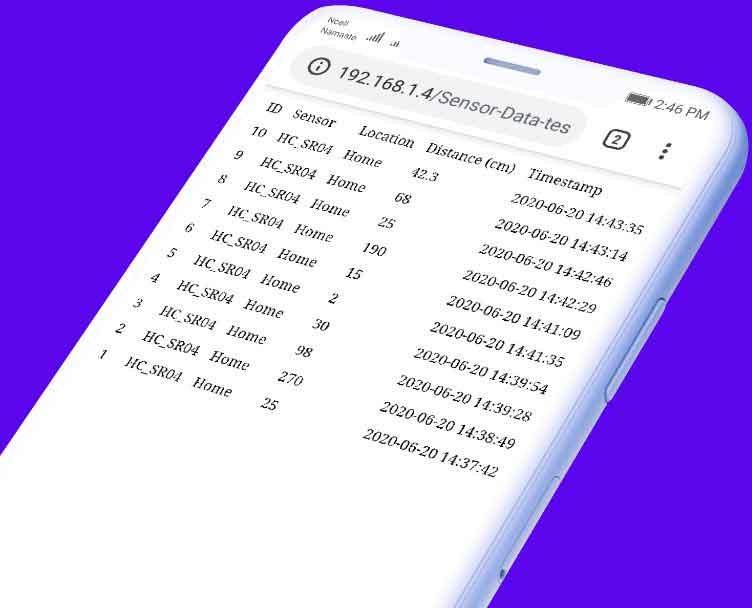
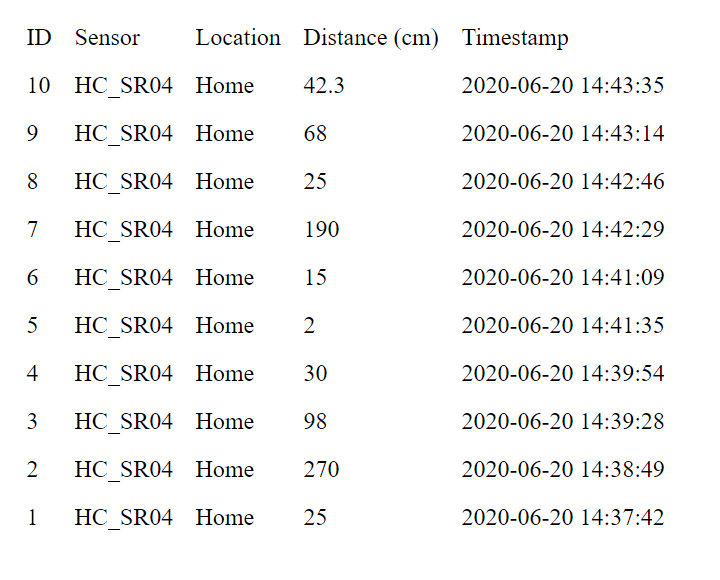
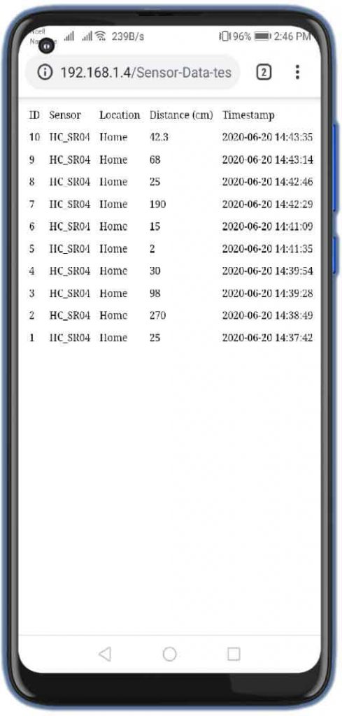
Now, when we see our PHP page at “http://192.168.1.4/Sensor-data-test/post-sensor-data.php“, the results of the listing will be displayed.
Some Frequently Asked Questions:
Sometimes error code-1 is printed in the Arduino IDE Serial Monitor, but the data is still inserted into the server.
If your server is not receiving the data, make sure you have the right files saved in your server (/sensor-data.php and post-sensor-data.php)
If you are using Domain and Hosting. You need to save all the PHP files in the root directory of public_html.
If you are using Xampp server. You need to save all those PHP files in C:xampphtdocsYour-Folder-Name.
Try to check your server name, it should be starting with “http://…” not “https://..” There is separate method for HTTPS Request. Check twice when you just copy & paste the host address.
You can define your server with HTTPS to have all data posted to your server encrypted. Of course, with this example, you are relying on third-party websites, but I’ve been using it for years and haven’t had any problem.
The URL /sensor-data.php is currently open to the public, but you can set up a login system with a PHP code that would keep that data private to you.
ou’ve to add some extra lines of code to adjust the time to your timezone in the sensor-data.php file:
You can simply add one of the following lines to adjust the time displayed in your webpage:
(you can change 1 to any number)
$row_reading_time = date(“Y-m-d H:i:s”, strtotime(“$row_reading_time – 1 hours”));
(you can change 4 to any number)
$row_reading_time = date(“Y-m-d H:i:s”, strtotime(“$row_reading_time + 4 hours”));
If the actual time (minute and date) is incorrect when inserting data into the database, I recommend contacting your host directly to see what is going on in your server.
I hope this solves your problem.
Yes. That was randomly generated. You can set any API Key that you want.
That way, only who knows the API key can post data to your database.
Conclusion
In this tutorial, we have shown you how to Insert Data into MySQL Database with the ESP8266 Development Board. Now you can modify this project and add any other sensor to read data in charts. I hope you enjoyed reading this article. If you need any type of help related to this project then do let me know in the comment section below.
You might also like reading:
- IoT Based RFID Smart Door Lock System Using NodeMCU ESp8266
- IoT Based LED Control using Google Firebase & ESP8266
- RFID Based Attendance System Using NodeMCU with PHP Web App
- NodeMCU ESP8266 Monitoring DHT11/DHT22 Temperature and Humidity with Local Web Server
- IoT Based Voice Controlled Home Automation Using NodeMCU & Android
- Dual Axis Solar Tracker Arduino Project Using LDR & Servo Motors
- Home Automation with MIT App Inventor and ESP8266


That code is vulnerable to sql injections. You should use prepared statements
Thanks for your suggestions. We should take care of security as well. But this is just a demo.
Was not able to get data in mysql db. Even though it is a good effort and everything is written so systematic but I think something is going wrong. Already tried many times but error code -1 keeps coming.
Please check your PC IP address the IP address of PC changes when Router is rebooted.
Hi Alsan, thanks for your prompt reply. I have taken up a domain where I am trying to implement it in Public HTML. Now I am getting HTTP Response code: 404 on serial monitor. It looks like domain is not visible, I am trying to rectify this.
Secondly please advise what will be the right POST request for POSTMAN testing.
I am struggling with this for weeks now, kindly help!
Hi, I keep getting this error ” mysqli::__construct(): The server requested authentication method unknown to the client [sha256_password]” eventhough I already followed your instructions and also my sensor’s data could not be read. Can you please help me?
must we use apikey?
Data not recieve from node mcu how to fix it