As those of us who are engaged in the forepart of the IoT revolution can imagine, there are numerous ways in which IoT can be of greater service in handling future epidemic or pandemic disease outbreaks. Certainly, many smart connected technologies are already at work. However, more than this can be done. Here, we learn about How IoT can help within the Covid-19 crisis. We have some of the subsequent healthcare IoT strategies that could improve our response time interval and quality of response to future outbreaks.
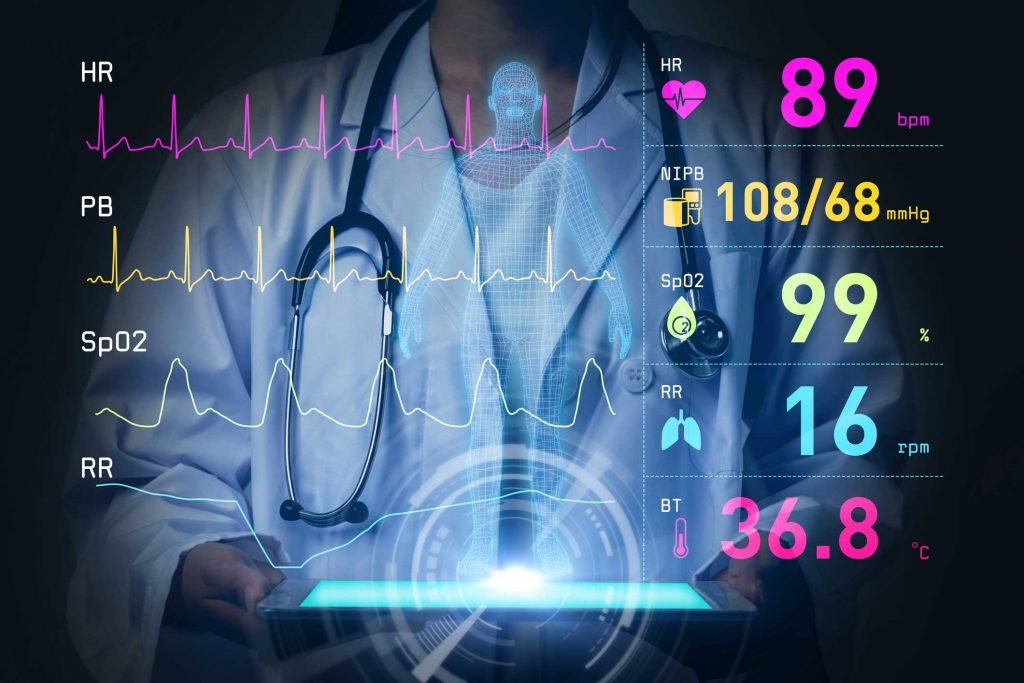
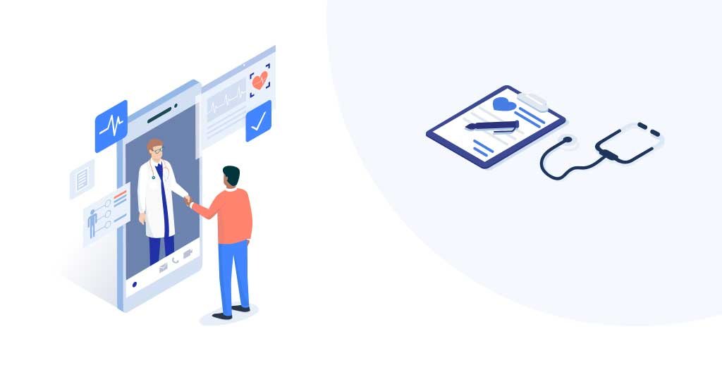
Smart connected devices to remotely monitor health conditions and vital sign of the patients
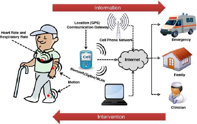
Devices that will remotely sense data like body temperature for all members of the house might be a very important technological development because elevated body temperature is one of the key signs of the onset of a virus-like COVID-19. The widespread deployment of IoT remote sensors to monitor body temperatures and changes in body temperatures could help identify potential hot spots within the population. for instance, the media has recently been talking about the health technology company Kinsa’s smart thermometer that crowdsources fevers and might help to predict outbreaks in particular geographical locations.
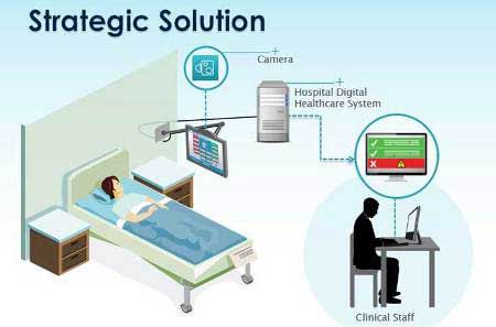
Improved telemedicine tools to reduce the amount of health care workers within the vicinity of the infected
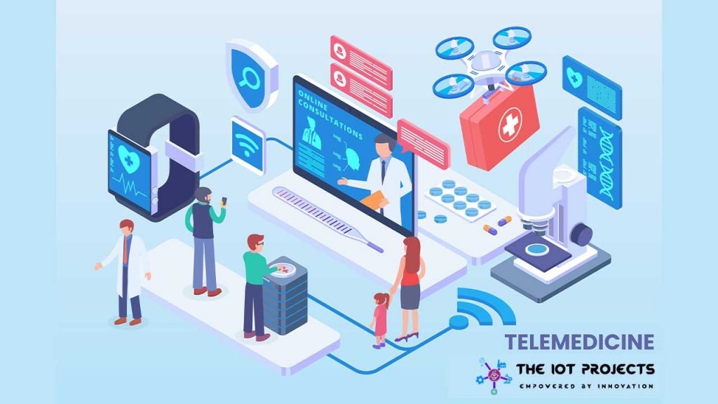
Minimizing the number of healthcare professionals within the vicinity of positively infected individuals is of key importance. what’s needed is an IoT solution that allows one healthcare professional within the vicinity of the patient to be networked with and become the eyes and ears of a bigger network of healthcare service providers. Head-mounted smart-connected camera technology would enable this in a manner that keeps the healthcare worker’s hands unengaged to do their job while being in communication audibly and visually with remote staff.
Widely-dispersed data acquisition apps for the capture of anecdotal information
IoT technology could also gather and process the vast amounts of anecdotal data associated with patient symptoms and also the effects of remediation techniques deployed to stem the tide of the virus. An example of this is able to be capturing the anecdotal experiences of all the individuals using anti-malarial drugs.
Though not intended to fight COVID-19, many doctors are prescribing such medications to patients with the hope that they might be helpful. Such individuals might not be a part of any formal FDA invoked clinical trial; however, capturing such anecdotal experiences could prove helpful for rapid assessment of efficacy and safety.
Smart monitoring of apparatus and consumables and matching to needs
We are hearing daily about the shortages of personal protective equipment (PPE) and ventilators, which are all required to assist improve patient outcomes and to drive safely for healthcare workers and others in touch with patients. RFID tagged consumables and MedTech hardware deployed with a strong tag- sensing infrastructure and tied to data analytics, could help make sure that the proper materials are in the right place at the correct time.
As things stand now, it’s likely that there are supply surpluses in locations not in need of reserves of PPE and ventilators, while other locations are critically short. trend analysis tied to a better understanding of the number of patients actively in need at any given time and therefore the anticipated change within the number of patients tied to the availability can ensure that the proper materials are existing when needed. The IoT sensing of equipment and consumables are often a critical part of this solution.
Read More: Introduction to The Internet Of Things (IoT)
Also Read: The Internet of Things: Needs, Benefits and Features
Monitoring the flow of those testing positive for COVID-19
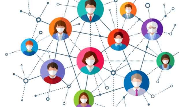
This is the one nobody wants to know about it, about, but, civil liberties aside, IoT technology exists in smartphones, watches, and tablets to trace the movement of these who are diagnosed as positive for COVID-19. it’s well known that quarantine of those testing positive is very important. Basically, The devices everyone carries are in essence IoT data acquisition devices for location tracking of patients. So, this is How can IoT help within the COVID-19 crisis.
IoT promises better preparedness for future outbreaks
While the technologies described here aren’t widely in use today, it’s not an enormous breakthrough to organize the infrastructure for a future outbreak, or maybe to start using them now and reaping the potential benefits for patients. IoT technologies could help us to prepare for future disruptive pandemics. Virus DNA is extremely malleable and adaptable to survival and propagation in ways not yet well understood. When the smoke starts to clear from the main focus on the most immediate crucial needs – including PPE and ventilators — there’ll be opportunities to boost the flexibility to trace the progression of the disease, provide crucial data for remediation strategies and distribute crucially needed resources.
Here we go: Top 10 IoT (Internet of Things) Projects
Many healthcare and tech companies are actively pursuing solutions to produce relief during the current pandemic, and looking out to the future with the hope that everybody can work together to avert a number of the present shortcomings and shortages facing healthcare providers and their patients who test positive for COVID-19. IoT technology currently plays a role in healthcare and will play an excellent more important role in future solutions. If we are able to all band together to share and learn from one another, we will improve future healthcare outcomes. So this is How can IoT help within the COVID-19 crisis. I hope you like this article.