Arduino Breathalyzer using MQ3 Sensor and OLED Display
DIY Breathalyzer using Arduino and MQ3 Sensor with OLED Display
Overview: Arduino Breathalyzer with MQ3 Sensor
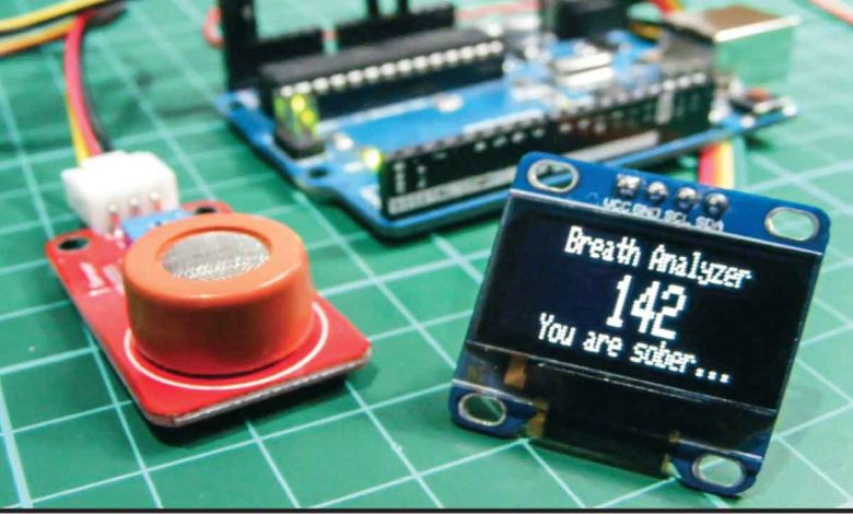
Today in this project we are going to make Arduino based breathalyzer using an MQ3 alcohol sensor and an OLED Display. We can see the number of drink and drive cases in our daily life. We cannot stop people from drinking alcohol but we can minimize such accidents by keeping this simple mini breathalyzer in vehicles. It alerts you when alcohol is detected by the sensor. We can also stop the vehicle if alcohol is detected by the sensor. So this is a mini project of Arduino Breathalyzer using MQ3 Sensor and OLED Display.
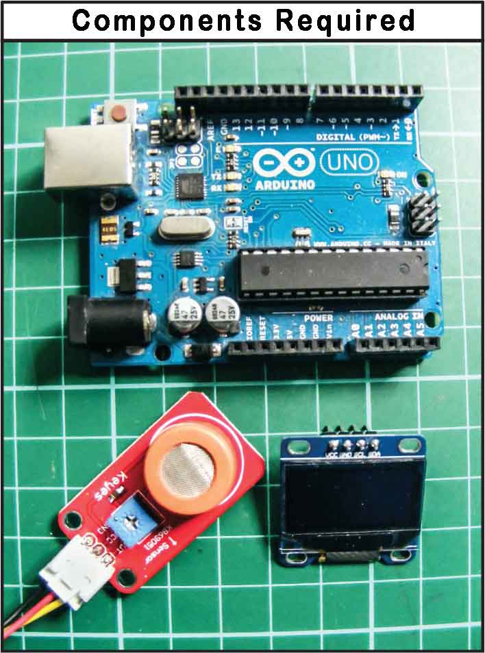
Components Required
The components required for making Arduino based Breathalyzer are provided below. You can easily purchase them from Amazon links.
| S.N | Components Name | Quantity | |
|---|---|---|---|
| 1 | Arduino UNO REV3 | 1 | https://amzn.to/3c6weVM |
| 2 | MQ3 Alcohol Sensor | 1 | https://amzn.to/3wFM4QN |
| 3 | 0.96" I2C OLED Display | 1 | https://amzn.to/3kvENyc |
| 6 | Few jumpers wires | 10 | https://amzn.to/3klh0A4 |
How Arduino based Breathalyzer works?
MQ3 is part of a family of gas sensors. MQ2 sensor is sensitive to methane, butane, and smoke. MQ4 sensor is sensitive to compressed natural gas. MQ6 is sensitive to butane and LPG gas. Similarly, the MQ7 sensor is sensitive to carbon monoxide. The MQ3 sensor is sensitive to alcohol and ethanol. Hence it’s a perfect sensor to use in our Arduino breathalyzer.
DISCLAIMER
This project is for education purposes only and should not be used to accurately determine anyone’s alcohol intake.
The MQ3 sensor has 3-pin or 4-pin connections on the module. They are analog OUT/Digital OUT, VCC, and GND. In most MQ sensors, the module has a small heater inside and an electrochemical sensor to measure the gas level. It sends the value of the reading to the OUT pin, which is then read by an analog pin on our Arduino.
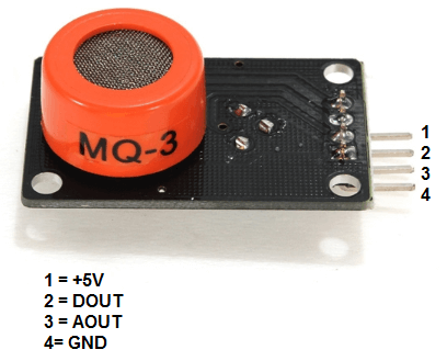
Now let’s have a look at the pinout.
| VCC | Supplies power for the module. You can connect it to 5V output from your Arduino |
| GND | It is the Ground Pin and needs to be connected to the GND pin on the Arduino |
| D0 | Provides a digital representation of the presence of alcohol |
| A0 | Provides analog output voltage in proportional to the concentration of alcohol |
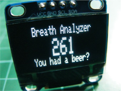
To display the sensor readings, we’ll use an OLED screen as shown below. OLED, which stands for organic light-emitting diode. It is a light-emitting technology composed of a thin multi-layered organic film placed between an anode and cathode. When voltage is applied, an image is created through electroluminescence. which means the screen does not require a backlight. Our OLED screen is an I2C 128×64 monochrome version. So we can control it using only two pins to the Arduino. It has 128 pixels by 64 pixels. When the MQ3 reads the value, the Arduino sends a message to the OLED screen showing whether alcohol has been detected.
WARNING
As mentioned earlier, the MQ3 uses an internal heater as part of the sensor process. This heater can reach 120–140 degrees when powered, so take care when handling it when it’s in use.
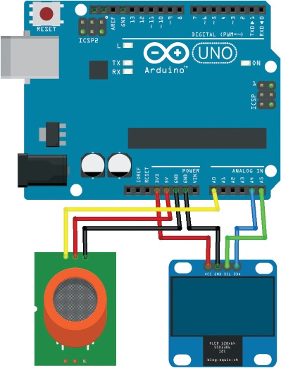
Circuit Diagram & Assembly
1. Before you use the sensor for the first time, you need to “burn it in.” This process, which simply involves powering it up for a few hours to heat the mechanism inside. This will improve the sensor’s accuracy. To do this, connect the VCC and GND pins of the sensor to +5V and GND on your Arduino, respectively. You can use female-to-male jumper wires. When you power the Arduino, it will send the correct voltage to the MQ3. Leave it powered for two to three hours—you may notice a burning smell and the sensor will get hot, but this is normal.
2. Once the sensor is burned in, disconnect the power to the Arduino. Now again connect the sensor to the Arduino using the female-to-male jumper wires, with the MQ3’s OUT pin connected to Arduino pin A0, and the power and GND still connected as before (see the following table).
| S.N | MQ-3 Sensor | Arduino |
| 1 | VCC | 5V |
| 2 | GND | GND |
| 3 | A0 | Pin A0 |
3. Next, connect the OLED screen to the Arduino as shown in the following table, with SCL connected to pin A5, SDA to pin A4, VCC to +3.3V, and GND to GND.
| S.N | OLED Display | Arduino |
| 1 | VCC | 3.3V |
| 2 | GND | GND |
| 3 | SCL | Pin A5 |
| 4 | SDA | Pin A4 |
4. This project requires several libraries to work correctly; the SPI and Wire libraries are built into the Arduino IDE, but we also need the Adafruit_GFX and Adafruit_SSD1306 libraries to control the OLED screen. Both are available on Arduino IDE Library Manager.
5. Check that your setup matches the circuit diagram below. Following is the circuit diagram for the OLED breathalyzer using Arduino and MQ3 sensor.
6. The heater inside the MQ3 sensor needs to heat for about 4 minutes before it can operate accurately. The sketch has a timer so that when you power it up for the first time, the values won’t appear on screen until the required time has passed. The “Warming up” text will display with a small countdown bar until the sensor is ready.
Project PCB Gerber File & PCB Ordering Online
I have assembled the circuit on a breadboard. If you don’t want to assemble the circuit on a breadboard and want Custom PCB for the project, then here is the PCB for you. The PCB Board for the portable Arduino Radar is designed for you. You can simply download the Gerber file from the link below and order the PCB online from PCBWay

PCBWay offers Only $5 for 10 PCBs and a total of $30 dollars for 20 PCBs Assembly. Apart from this PCBWay offers $5 as a signup bonus. So, what are you waiting for? get your first prototype order for free.
Also Read:
- Alcohol Detector Using Arduino & MQ3 Sensor
- Getting Started with Arduino UNO
- Power Supply board for NodeMCU ESP8266
- BMP280 Based Weather Station using Arduino and OLED Display
- Pulse Oximeter using Arduino & MAX30100
Program/Source Code
The program code starts by including the SPI, Wire, Adafruit_GFX, and Adafruit_SSD1306 libraries to control communication and the OLED screen.
#include <SPI.h>
#include <Wire.h>
#include <Adafruit_GFX.h>
#include <Adafruit_SSD1306.h>
We assign a time for the warm-up session (4 minutes) and set the analog pin as Arduino A0.
int TIME_UNTIL_WARMUP = 4; // Time for the warm-up delay in minutes
unsigned long time;
int analogPin = 0; // Set analog pin as A0
int val = 0; // Set a value to read from the analog pin
Next, we set up the OLED screen. The Arduino sends different messages to the screen depending on the value read from the analog pin. For instance, if the sensor reading is above 200, the Arduino will ask you if you’ve had a beer. If the reading is below this value, the Arduino will say you’re sober. The minimum level of alcohol the MQ3 will read is about 180. For anything over 450, the breathalyzer will let you know you’re drunk!
// Call the SPI, Wire, Adafruit_GFX, and Adafruit_SDD1306 libraries
#include <SPI.h>
#include <Wire.h>
#include <Adafruit_GFX.h>
#include <Adafruit_SSD1306.h>
#define OLED_RESET 4 // Define the OLED screen
int TIME_UNTIL_WARMUP = 4; // Time for the warm-up delay in minutes
unsigned long time;
int analogPin = 0; // Set analog pin as A0
int val = 0; // Set a value to read from the analog pin
Adafruit_SSD1306 display(OLED_RESET);
void setup() { // Set up the OLED screen
display.begin(SSD1306_SWITCHCAPVCC, 0x3C);
display.clearDisplay();
}
void loop() { // Take the reading and show it onscreen
delay(100);
val = readAlcohol();
printTitle();
printWarming();
time = millis() / 1000;
time /= 60;
if (time <= TIME_UNTIL_WARMUP) { // If warm-up is less than 4 mins
time = map(time, 0, TIME_UNTIL_WARMUP, 0, 100); // Show countdown
display.drawRect(10, 50, 110, 10, WHITE); // Empty bar
display.fillRect(10, 50, time, 10, WHITE);
} else { // When warm-up time has passed
// the value and message are printed on the screen
printTitle();
printAlcohol(val);
printAlcoholLevel(val);
}
display.display();
}
void printTitle() { // Position and text of title on the screen
display.clearDisplay();
display.setTextSize(1);
display.setTextColor(WHITE);
display.setCursor(22, 0);
display.println("Breath Analyzer");
}
void printWarming() { // Warm-up message
display.setTextSize(1);
display.setTextColor(WHITE);
display.setCursor(30, 24);
display.println("Warming up");
}
void printAlcohol(int value) { // Print alcohol value to screen
display.setTextSize(2);
display.setTextColor(WHITE);
display.setCursor(50, 10);
display.println(val);
}
void printAlcoholLevel(int value) { // Print message to screen
display.setTextSize(1);
display.setTextColor(WHITE);
display.setCursor(20, 25);
if (value < 200) { // If value read is less than 200, you are sober
display.println("You are sober...");
}
if (value >= 200 && value < 280) {
display.println("You had a beer?");
}
if (value >= 280 && value < 350) {
display.println("Two or more beers.");
}
if (value >= 350 && value < 450) {
display.println("I smell VODKA!");
}
if (value > 450) {
display.println("You are drunk!");
}
}
// Finds average by summing three readings and
// dividing by 3 for better accuracy
int readAlcohol() {
int val = 0;
int val1;
int val2;
int val3;
display.clearDisplay();
val1 = analogRead(analogPin);
delay(10);
val2 = analogRead(analogPin);
delay(10);
val3 = analogRead(analogPin);
val = (val1 + val2 + val3) / 3;
return val;
}
The program loops every second to read the analog sensor. To use the breathalyzer, wait for the sensor to heat for 4 minutes, then gently breathe onto the sensor. Try not to get the sensor wet or expose it to a smoky environment, as this will affect the reading.
Video Tutorial & Guide
Wrapping Up
So, that’s all for Arduino Breathalyzer using MQ3 Sensor and OLED Display that can be can be used in a variety of locations. I wish you all the best for the project. if you are stuck anywhere you can ask me in the comment section below.
Q. The display is not showing readings correctly.
- Recheck that your wiring matches the above diagram.
- If all your wiring is in the correct place, make sure you’ve carried out the earlier step to burn the sensor in by leaving it powered for a few hours.
- To check whether your components are faulty, temporarily swap a potentiometer in for the sensor. Connect the center pin of the potentiometer to A0 and add power to either side. If the potentiometer is working okay, it means your sensor is probably faulty, so replace your sensor—they are very inexpensive.