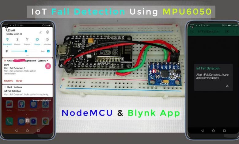
As we all know the fall detector system is very useful for older people. This is because it can notify the individual or family member when it detects a fall and reduces the risk of delay in medical attention. So it leads to the development of various types of automatic fall detector systems. Nowadays, we can also find fall detectors in smartwatches, fitness trackers, and other types of wearables. IoT-based fall detector devices can save lives in an emergency. So in today’s tutorial, we are going to build an IoT Fall Detector Using MPU6050, NodeMCU ESP8266, and Blynk Application.
The MPU6050 sensor module has a built-in gyroscope and an accelerometer sensor. The gyroscope is used to determine the orientation and the accelerometer provides information about the angle, such as X, Y, and Z-axis data. To detect the fall, we will compare the acceleration magnitude with the threshold value. If a fall is detected, the device sends a notification and email to the concerned person. NodeMCU ESP8266 is used here as a microcontroller and Wi-Fi module to send a notification with Blynk IoT App.
Components Required
The following are the components required for the IoT Fall Detector system. You can buy them from the amazon link provided below:
| S.N | Components | Description | Quantity | |
|---|---|---|---|---|
| 1. | NodeMCU | ESP8266 12E Board | 1 | https://amzn.to/3mTuL95 |
| 2. | MPU6050 6-axis Gyroscope/Accelerometer | Gyroscope + Accelerometer | 1 | https://amzn.to/39OEuKk |
| 3. | Breadboard | Solderless Breadboard MIni | 1 | https://amzn.to/3n33uRT |
| 4. | Jumper Wires | Connecting Wires | 4 | https://amzn.to/2JWSR44 |
MPU6050 Sensor Module
The MPU6050 sensor module is a 6-axis (3- axis accelerometer and 3- axis gyroscope) module. A micro-electro-mechanical system (MEMS) is used to measure velocity, acceleration, orientation, displacement, and many other motion-related parameters. Besides, it has an additional built-in temperature sensor.
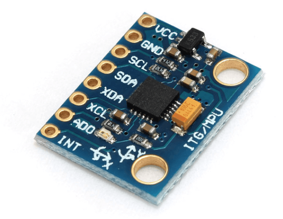
The MPU6050 module is small in size with small power consumption. Also, it has high iteration, high shock tolerance, and low user value points. Typically, the MPU6050 comes with an I2C and auxiliary I2C interfaces. So it can easily interfere with other sensors like magnetometers and microcontrollers.
Interfacing MPU6050 Sensor with NodeMCU ESP8266
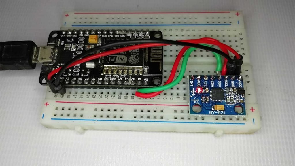
The circuit diagram for IoT Fall Detector Using MPU6050 & ESP8266 NodeMCU is provided below.
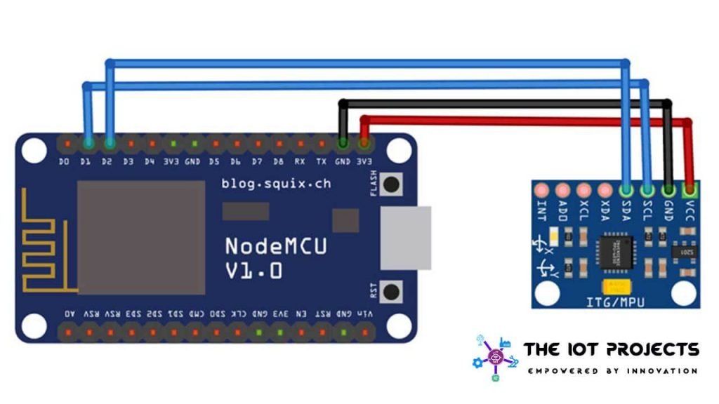
The MPU6050 works on the I2C protocol, so we only need two wires to interface the NodeMCU and the MPU6050. The SCL and SDA pins of the MPU6050 are connected to the D1 and D2 pins of the NodeMCU, while the VCC and GND pins of the MPU6050 are connected to the 3.3V and Ground pin of NodeMCU.
PCB Designing & Ordering Online
This projects looks beautiful with a custom PCB. You can use an EasyEDA online Circuit Schematics & PCB designing tool to design a schematic and download the Gerber file.

Go to the NextPCB official website and order the PCB at a very cheap price. All you need is to upload the Gerber file, then view your PCB in Gerber viewer. Select the details like PCB Quantity, color, and thickness. Now select your country of shipment and place an order. The PCB quality is clean, brilliant & of high quality. That is why most people trust NextPCB for PCB & PCBA Services.
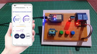
Blynk IoT Cloud Setup for IoT Fall detector
I have done many projects related to IoT with the Blynk application and designed many apps before. In this session, I am designing IoT based Fall Detector App. So, Make sure you download and install the Blynk app from Playstore/Appstore.
- First of all, open the blynk application.
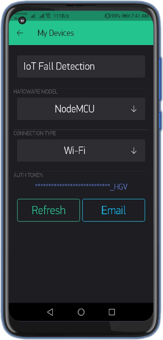
- Click on the create a new project and enter the project name as “IoT Fall Detector“. Instead, you can type any name. You can change the name later.
- Click on Choice Tools and select NodeMCU ESP8266.
- Make sure the connection type is set to WIFI.
- Finally, click on the create button, a verification token will be sent to your email ID, which will be used in the Program CODE.
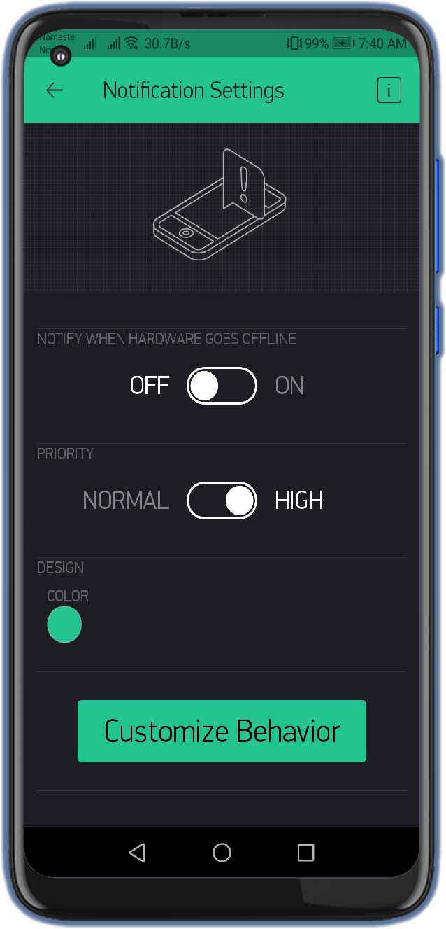
- Click + icon on the screen, and search for the Notification and Email Widget. Add them to your Blynk App. Now the application for IoT Fall Detection is ready to use.

Note: When you have finished all the Blynk IoT cloud connection parts, let’s go to the programming part to ensure your Blynk Authentication token, WiFi SSID, and password are correct. When you have finished all these parts, be sure to select the correct COM port and board for uploading the code.
Recommended Projects:
- Insert Data into MySQL Database with ESP8266 Development Board
- Monitor MPU6050 Tilt Angle on Blynk using NodeMCU
- IoT based Fall Detection using NodeMCU and IFTTT
- Home Automation with MIT App Inventor and ESP8266
- IoT Based LED Control using Google Firebase & ESP8266
- Alcohol Detector Using Arduino & MQ3 Sensor
- IoT based Fire Detector & Automatic Extinguisher using NodeMCU
- Portable Radar Using Arduino
Program Code Explanation
The complete code for IoT Fall Detector Using MPU6050 & ESP8266 is provided at the end of this code explanation. Here we are describing some important parts.
As usual, we started by including all the necessary libraries of code. The Wire. h library helps communicate with I2C devices while the ESP8266WiFi.h library provides the ESP8266 with a specific Wi-Fi routine that we are calling to connect to the network.
 #include <Wire.h>
 #define BLYNK_PRINT Serial
 #include <ESP8266WiFi.h>
 #include <BlynkSimpleEsp8266.h>
At this stage, we have provided Wi-Fi SSID, password, and Blynk IoT cloud Authentication token credentials
char auth[] = "DvB2bleEr8jChdq9OTA5AfhoCHsc_HGV"; //Auth code sent via Email
const char *ssid = "Alsan Air WiFi 1"; // Enter your Wi-Fi Name
const char *pass = ""; // Enter your Wi-Fi Password
Within void setup, we have started serial monitor at a baud rate of 115200. We also initialize the blynk library with an authentication process. Data transmission through the wire library and power management register has also been started.
void setup() {
   Serial.begin(115200);
   Blynk.begin(auth, ssid, pass);
   Wire.begin();
   Wire.beginTransmission(MPU_addr);
   Wire.write(0x6B);  // PWR_MGMT_1 register
   Wire.write(0);     // set to zero (wakes up the MPU-6050)
   Wire.endTransmission(true);
   Serial.println("Wrote to IMU");
   Serial.println("Connecting to ");
   Serial.println(ssid);
   WiFi.begin(ssid, pass);
   while (WiFi.status() != WL_CONNECTED)
   {
     delay(500);
     Serial.print(".");              // print … till not connected
   }
   Serial.println("");
   Serial.println("WiFi connected");
 }
Now inside the void loop, Blynk.run is initialized and we read the MPU6050 sensor data. 2050, 77, 1947 are the values for the calibration of an accelerometer. The value is the same as for the gyroscope, add calibration values to the original values.
void loop() {
   Blynk.run();
   mpu_read();
   ax = (AcX - 2050) / 16384.00;
   ay = (AcY - 77) / 16384.00;
   az = (AcZ - 1947) / 16384.00;
   gx = (GyX + 270) / 131.07;
   gy = (GyY - 351) / 131.07;
   gz = (GyZ + 136) / 131.07;
After getting the accelerometer and gyroscope values, calculate the amplitude vector of the accelerometer values.
// calculating Amplitute vactor for 3 axis
   float Raw_Amp = pow(pow(ax, 2) + pow(ay, 2) + pow(az, 2), 0.5);
   int Amp = Raw_Amp * 10;  // Mulitiplied by 10 bcz values are between 0 to 1
   Serial.println(Amp);
This program first checks if the accelerometer value is higher than the lower threshold, if so, then it waits for half a second and checks for higher thresholds. If the accelerometer value exceeds the upper threshold, then it calculates the change in orientation for the gyroscope values. When there is a sudden change in orientation, it waits for 10 seconds and checks if the orientation remains the same.
if (Amp <= 2 && trigger2 == false) { //if AM breaks lower threshold (0.4g)
trigger1 = true;
Serial.println("TRIGGER 1 ACTIVATED");
}
if (trigger1 == true) {
trigger1count++;
if (Amp >= 12) { //if AM breaks upper threshold (3g)
trigger2 = true;
Serial.println("TRIGGER 2 ACTIVATED");
trigger1 = false; trigger1count = 0;
}
}
if (trigger2 == true) {
trigger2count++;
angleChange = pow(pow(gx, 2) + pow(gy, 2) + pow(gz, 2), 0.5); Serial.println(angleChange);
if (angleChange >= 30 && angleChange <= 400) { //if orientation changes by between 80-100 degrees
trigger3 = true; trigger2 = false; trigger2count = 0;
Serial.println(angleChange);
Serial.println("TRIGGER 3 ACTIVATED");
}
}
if (trigger3 == true) {
trigger3count++;
if (trigger3count >= 10) {
angleChange = pow(pow(gx, 2) + pow(gy, 2) + pow(gz, 2), 0.5);
//delay(10);
Serial.println(angleChange);
if ((angleChange >= 0) && (angleChange <= 10)) { //if orientation changes remains between 0-10 degrees
fall = true; trigger3 = false; trigger3count = 0;
Serial.println(angleChange); }
else { //user regained normal orientation
trigger3 = false; trigger3count = 0;
Serial.println("TRIGGER 3 DEACTIVATED");
}
}
}
if (fall == true) { //in event of a fall detection
Serial.println("FALL DETECTED");
Blynk.notify("Alert : Fall Detected…! take action immediately."); Blynk.email("ask.theiotprojects@gmail.com", "Alert : Fall Detected…!", "Alert : Fall Detected…! take action immediately.");
fall = false;
}
if (trigger2count >= 6) { //allow 0.5s for orientation change
trigger2 = false; trigger2count = 0;
Serial.println("TRIGGER 2 DECACTIVATED");
}
if (trigger1count >= 6) { //allow 0.5s for AM to break upper threshold
trigger1 = false; trigger1count = 0;
Serial.println("TRIGGER 1 DECACTIVATED");
}
delay(100);
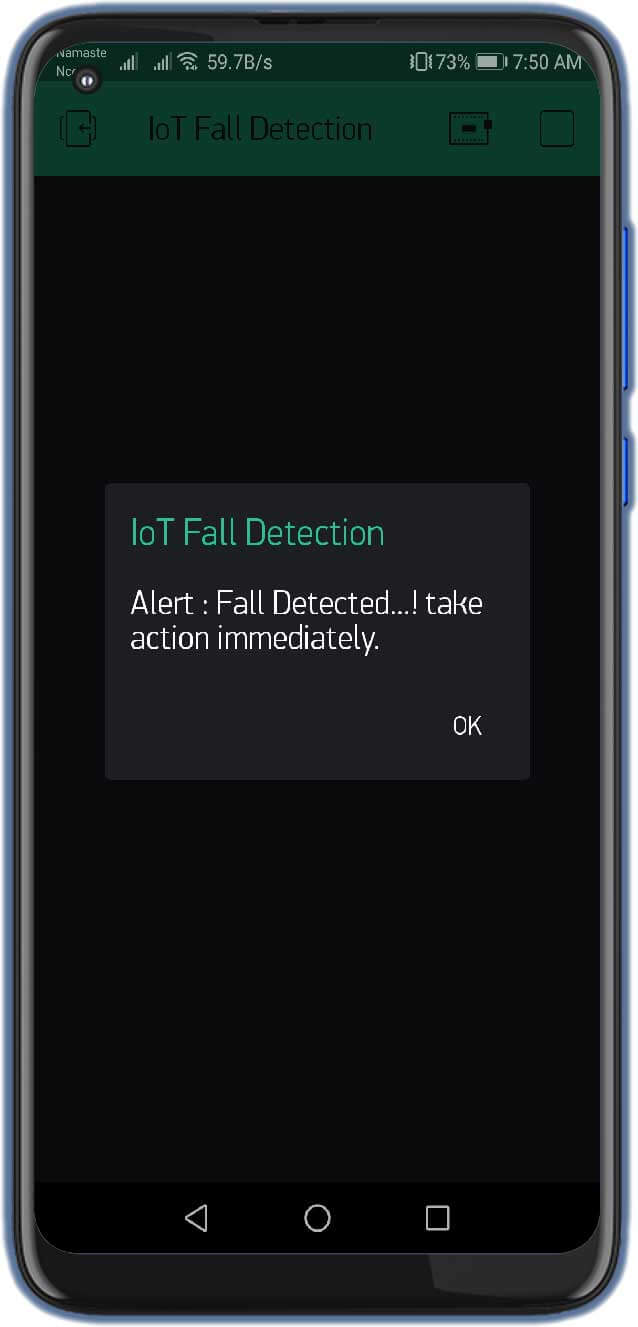
}If so, the fall detector activates the notification and send email to the provided email address.
if (fall == true) { //in event of a fall detection
Serial.println("FALL DETECTED");
Blynk.notify("Alert : Fall Detected…! take action immediately.");
Blynk.email("ask.theiotprojects@gmail.com", "Alert : Fall Detected…!", "Alert : Fall Detected…! take action immediately.");
fall = false;
}
Within the mpu_read loop (), read all six registers for the X, Y, and Z axes of the accelerometer and gyroscope.
void mpu_read() {
   Wire.beginTransmission(MPU_addr);
   Wire.write(0x3B);  // starting with register 0x3B (ACCEL_XOUT_H)
   Wire.endTransmission(false);
   Wire.requestFrom(MPU_addr, 14, true); // request a total of 14 registers
   AcX = Wire.read() << 8 | Wire.read(); // 0x3B (ACCEL_XOUT_H) & 0x3C (ACCEL_XOUT_L)
   AcY = Wire.read() << 8 | Wire.read(); // 0x3D (ACCEL_YOUT_H) & 0x3E (ACCEL_YOUT_L)
   AcZ = Wire.read() << 8 | Wire.read(); // 0x3F (ACCEL_ZOUT_H) & 0x40 (ACCEL_ZOUT_L)
   Tmp = Wire.read() << 8 | Wire.read(); // 0x41 (TEMP_OUT_H) & 0x42 (TEMP_OUT_L)
   GyX = Wire.read() << 8 | Wire.read(); // 0x43 (GYRO_XOUT_H) & 0x44 (GYRO_XOUT_L)
   GyY = Wire.read() << 8 | Wire.read(); // 0x45 (GYRO_YOUT_H) & 0x46 (GYRO_YOUT_L)
   GyZ = Wire.read() << 8 | Wire.read(); // 0x47 (GYRO_ZOUT_H) & 0x48 (GYRO_ZOUT_L)
 }
IoT Fall Detector Full Program code
This is the final program code for using the IoT-based Fall Detector using NodeMCU.
#include <Wire.h>
#define BLYNK_PRINT Serial
#include <ESP8266WiFi.h>
#include <BlynkSimpleEsp8266.h>
const int MPU_addr = 0x68; // I2C address of the MPU-6050
int16_t AcX, AcY, AcZ, Tmp, GyX, GyY, GyZ;
float ax = 0, ay = 0, az = 0, gx = 0, gy = 0, gz = 0;
boolean fall = false; //stores if a fall has occurred
boolean trigger1 = false; //stores if first trigger (lower threshold) has occurred
boolean trigger2 = false; //stores if second trigger (upper threshold) has occurred
boolean trigger3 = false; //stores if third trigger (orientation change) has occurred
byte trigger1count = 0; //stores the counts past since trigger 1 was set true
byte trigger2count = 0; //stores the counts past since trigger 2 was set true
byte trigger3count = 0; //stores the counts past since trigger 3 was set true
int angleChange = 0;
// WiFi network info.
char auth[] = "DvB2bleEr8jChdq9OTA5AfhoCHsc_HGV"; //Auth code sent via Email
const char *ssid = "Alsan Air WiFi 1"; // Enter your Wi-Fi Name
const char *pass = ""; // Enter your Wi-Fi Password
void setup() {
Serial.begin(115200);
Blynk.begin(auth, ssid, pass);
Wire.begin();
Wire.beginTransmission(MPU_addr);
Wire.write(0x6B); // PWR_MGMT_1 register
Wire.write(0); // set to zero (wakes up the MPU-6050)
Wire.endTransmission(true);
Serial.println("Wrote to IMU");
Serial.println("Connecting to ");
Serial.println(ssid);
WiFi.begin(ssid, pass);
while (WiFi.status() != WL_CONNECTED)
{
delay(500);
Serial.print("."); // print … till not connected
}
Serial.println("");
Serial.println("WiFi connected");
}
void loop() {
Blynk.run();
mpu_read();
ax = (AcX - 2050) / 16384.00;
ay = (AcY - 77) / 16384.00;
az = (AcZ - 1947) / 16384.00;
gx = (GyX + 270) / 131.07;
gy = (GyY - 351) / 131.07;
gz = (GyZ + 136) / 131.07;
// calculating Amplitute vactor for 3 axis
float Raw_Amp = pow(pow(ax, 2) + pow(ay, 2) + pow(az, 2), 0.5);
int Amp = Raw_Amp * 10; // Mulitiplied by 10 bcz values are between 0 to 1
Serial.println(Amp);
if (Amp <= 2 && trigger2 == false) { //if AM breaks lower threshold (0.4g)
trigger1 = true;
Serial.println("TRIGGER 1 ACTIVATED");
}
if (trigger1 == true) {
trigger1count++;
if (Amp >= 12) { //if AM breaks upper threshold (3g)
trigger2 = true;
Serial.println("TRIGGER 2 ACTIVATED");
trigger1 = false; trigger1count = 0;
}
}
if (trigger2 == true) {
trigger2count++;
angleChange = pow(pow(gx, 2) + pow(gy, 2) + pow(gz, 2), 0.5); Serial.println(angleChange);
if (angleChange >= 30 && angleChange <= 400) { //if orientation changes by between 80-100 degrees
trigger3 = true; trigger2 = false; trigger2count = 0;
Serial.println(angleChange);
Serial.println("TRIGGER 3 ACTIVATED");
}
}
if (trigger3 == true) {
trigger3count++;
if (trigger3count >= 10) {
angleChange = pow(pow(gx, 2) + pow(gy, 2) + pow(gz, 2), 0.5);
//delay(10);
Serial.println(angleChange);
if ((angleChange >= 0) && (angleChange <= 10)) { //if orientation changes remains between 0-10 degrees
fall = true; trigger3 = false; trigger3count = 0;
Serial.println(angleChange); }
else { //user regained normal orientation
trigger3 = false; trigger3count = 0;
Serial.println("TRIGGER 3 DEACTIVATED");
}
}
}
if (fall == true) { //in event of a fall detection
Serial.println("FALL DETECTED");
Blynk.notify("Alert : Fall Detected…! take action immediately.");
Blynk.email("ask.theiotprojects@gmail.com", "Alert : Fall Detected…!", "Alert : Fall Detected…! take action immediately.");
fall = false;
}
if (trigger2count >= 6) { //allow 0.5s for orientation change
trigger2 = false; trigger2count = 0;
Serial.println("TRIGGER 2 DECACTIVATED");
}
if (trigger1count >= 6) { //allow 0.5s for AM to break upper threshold
trigger1 = false; trigger1count = 0;
Serial.println("TRIGGER 1 DECACTIVATED");
}
delay(100);
}
void mpu_read() {
Wire.beginTransmission(MPU_addr);
Wire.write(0x3B); // starting with register 0x3B (ACCEL_XOUT_H)
Wire.endTransmission(false);
Wire.requestFrom(MPU_addr, 14, true); // request a total of 14 registers
AcX = Wire.read() << 8 | Wire.read(); // 0x3B (ACCEL_XOUT_H) & 0x3C (ACCEL_XOUT_L)
AcY = Wire.read() << 8 | Wire.read(); // 0x3D (ACCEL_YOUT_H) & 0x3E (ACCEL_YOUT_L)
AcZ = Wire.read() << 8 | Wire.read(); // 0x3F (ACCEL_ZOUT_H) & 0x40 (ACCEL_ZOUT_L)
Tmp = Wire.read() << 8 | Wire.read(); // 0x41 (TEMP_OUT_H) & 0x42 (TEMP_OUT_L)
GyX = Wire.read() << 8 | Wire.read(); // 0x43 (GYRO_XOUT_H) & 0x44 (GYRO_XOUT_L)
GyY = Wire.read() << 8 | Wire.read(); // 0x45 (GYRO_YOUT_H) & 0x46 (GYRO_YOUT_L)
GyZ = Wire.read() << 8 | Wire.read(); // 0x47 (GYRO_ZOUT_H) & 0x48 (GYRO_ZOUT_L)
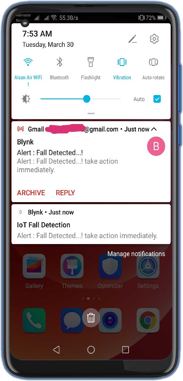
}Testing IoT Fall Detector Using MPU6050 & NodeMCU ESP8266
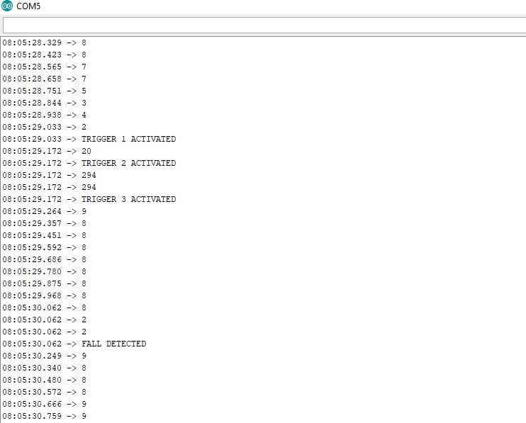
Upload the code, once your program code and hardware are ready. To test the project, take the MPU6050 in your hand and pretend to be walking slowly, and then suddenly drop it down as shown in the video. If the magnitude exceeds the threshold value, the device activates the fall detector event and sends a notification to the Blynk App and Email to the registered email address.
Conclusion
So, that’s pretty much for this tutorial. I hope you enjoyed creating your IoT Fall Detector Using MPU6050 & ESP8266 NodeMCU. If you did, don’t forget to share this article with your friends. Want help? let me know in the comment section below.


Hi i saw your video in youtube and it’s incredibe, but ‘m getting a bit of a problem the fall detected in serial monitor is showing but i’m not getting any notification and email on my phone
Have you changed authentication token and WiFi credentials? If yes, please provide background running permission to Blynk app as well
Hi thank you for your fast response i already did that . Should i change the blynk.email in the code to my email address? Or just the token and wifi
Yes you need to change the email address to your email address where you want to receive alert
Hi! Thank you for the very clear tutorial. As I am trying to run the code, it appears error “expected primary-expression before ‘.’ token”
What should I do sir?
how can I increases the sensitivity of the device, since in my case it takes a lot of attempts to detect it
compilation terminated.
exit status 1
Compilation error: ESP8266WiFi.h: No such file or directory
pleas help
In file included from c:UsersKIITDocumentsArduinolibrariesBlynksrc/BlynkApiArduino.h:14,
from c:UsersKIITDocumentsArduinolibrariesBlynksrc/BlynkSimpleEsp8266.h:24,
from C:UsersKIITAppDataLocalTemp.arduinoIDE-unsaved2024020-9192-1jueoc2.ce3zsketch_jan20asketch_jan20a.ino:5:
c:UsersKIITDocumentsArduinolibrariesBlynksrc/Blynk/BlynkApi.h:39:6: error: #error “Please specify your BLYNK_TEMPLATE_ID and BLYNK_TEMPLATE_NAME”
39 | #error “Please specify your BLYNK_TEMPLATE_ID and BLYNK_TEMPLATE_NAME”
| ^~~~~
exit status 1
Compilation error: exit status 1
sir what can be done for this type of error