QR Code Scanner with ESP32 CAM Module & OpenCV
Using OpenCV and ESP32 CAM Module to Scan QR Codes
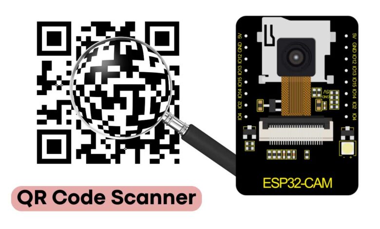
Overview: QR Code Reader using ESP32 Camera
This project aims to create a QR code scanner or reader using the ESP32 CAM module and OpenCV. By developing a program and device with Python libraries, we can easily scan QR codes using the ESP32 Camera module. This ESP32 CAM module provides a more affordable alternative.
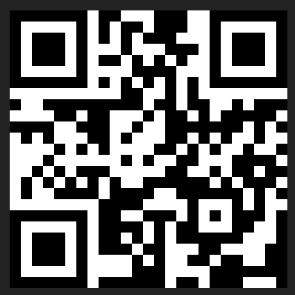
QR codes have become an integral part of our daily lives, as we use them for a variety of purposes, including payments, accessing websites, and sharing social profiles on resumes. Additionally, large tracking and shipping companies use QR codes to differentiate their products.
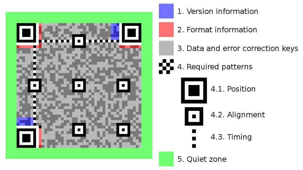
A QR code is a type of image that contains encoded information in a specific format that can be deciphered and decoded using a program. The decoding process involves detecting the different zones and aligning the dark boxes in a specific way. Each dark box represents a selection, with a value of 0, 1, 2, 4, 8, 16, 32, 64, or 128, among others.
Components Required
To build a QR Code scanner using the ESP32 CAM module, the following bill of materials is required. These components can be purchased from Amazon or other online retailers.
| S.N | COMPONENTS NAME | QUANTITY | PURCHASE LINKS |
|---|---|---|---|
| 1 | ESP32-CAM Board AI-Thinker | 1 | Amazon | AliExpress |
| 2 | FTDI Module | 1 | Amazon | AliExpress |
| 3 | Micro-USB Cable | 1 | Amazon | AliExpress |
| 4 | Jumper Cables | 10 | Amazon | AliExpress |
ESP32 CAM Module
The ESP32 CAM module, developed by AI-Thinker, is based on a 32-bit CPU and features a combined Wi-Fi and Bluetooth/BLE chip. It has 520 KB of built-in SRAM and an external 4M PSRAM. The module’s GPIO pins support various interfaces, including UART, SPI, I2C, PWM, ADC, and DAC.
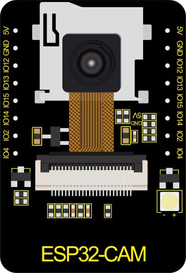
The module is equipped with the OV2640 camera module, which boasts the highest camera resolution of up to 1600 × 1200. The camera connects to the ESP32 CAM board via a 24-pin gold-plated connector. Additionally, the board supports SD cards of up to 4GB, which can be used to store captured images.
To learn more about the ESP32 Camera Module, you can refer to our previous Getting Started Tutorial.
ESP32-CAM FTDI Connection
The board does not have a programmer chip, so in order to program it, any USB-to-TTL module can be used. There are numerous FTDI modules available based on the CP2102 or CP2104 chip, among others.
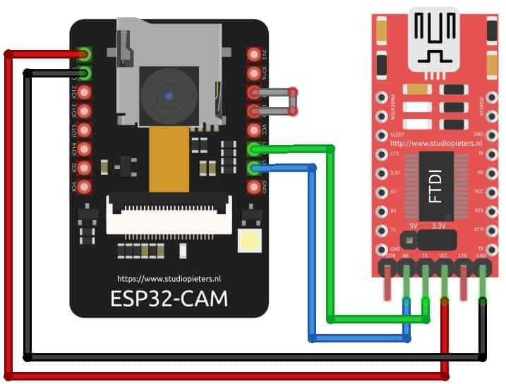
To connect the FTDI module to the ESP32 CAM module, make the following connections:
| ESP32-CAM | FTDI Programmer |
| GND | GND |
| 5V | VCC |
| U0R | TX |
| U0T | RX |
| GPIO0 | GND |
To connect the ESP32 module to the FTDI module, follow these steps: First, connect the 5V and GND pins of the ESP32 module to the 5V and GND pins of the FTDI module. Next, connect the Rx pin of the ESP32 module to the UOT pin of the FTDI module and the Tx pin of the ESP32 module to the UOR pin of the FTDI module.
Finally, it is essential to short the IO0 and GND pins together to put the device in programming mode. Once programming is complete, this connection can be removed.
Project PCB Gerber File & PCB Ordering Online
If you don’t want to assemble the circuit on a breadboard and you want a PCB for the project, then here is the PCB for you. The PCB Board for the Arducam Board looks something like the one below.
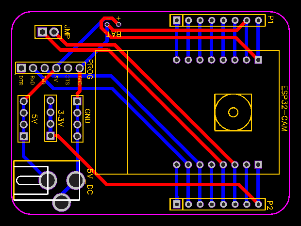
The Gerber File for the PCB is given below. You can simply download the Gerber File and order the PCB from https://www.pcbway.com/
Now you can visit the PCBWay official website by clicking here: https://www.pcbway.com/. So you will be directed to the PCBWay website.

You can now upload the Gerber File to the Website and place an order. The PCB quality is superb & high. That is why most people trust PCBWay for PCB & PCBA Services.
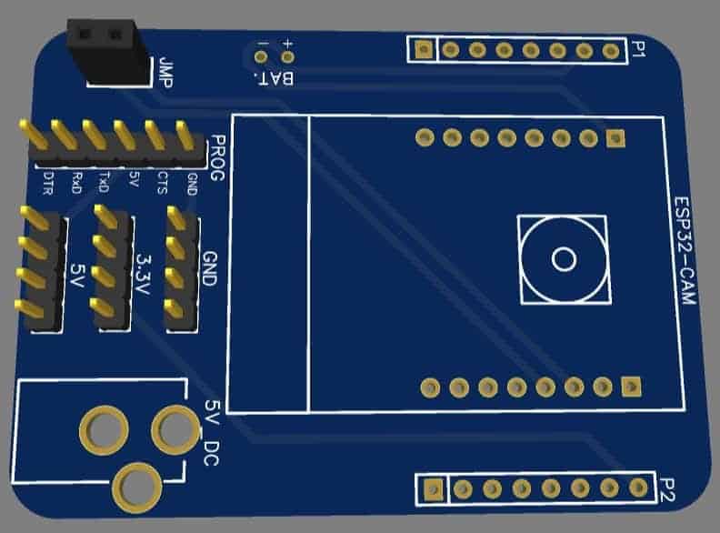
The two-dimensional view of the printed circuit board (PCB) is truly impressive. It has the potential to look lifelike once all the components have been assembled onto the PCB.
Installation of ESP32CAM Library
In this project, we will use a different streaming process than the general ESP webserver example. As a result, we need to add the ESPCAM library to our project. This library provides an object-oriented API for using the OV2640 camera on the ESP32 microcontroller, and it is a wrapper of the esp32-camera library.
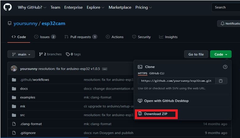
To download the ESPCAM library, go to the following GitHub link and download the zip file shown in the image. Once you have downloaded the library, add it to the Arduino Library Folder by following these steps: Open Arduino -> Sketch -> Include Library -> Add .ZIP Library… -> Navigate to downloaded zip file -> add.
ESP32 CAM Module Source Code/Program
Below is the source code for QR Code Scanner with the ESP32 CAM module. To use it, simply copy the code and paste it into the Arduino IDE.
#include <WebServer.h>
#include <WiFi.h>
#include <esp32cam.h>

const char* WIFI_SSID = "ssid";
const char* WIFI_PASS = "password";

WebServer server(80);


static auto loRes = esp32cam::Resolution::find(320, 240);
static auto midRes = esp32cam::Resolution::find(350, 530);
static auto hiRes = esp32cam::Resolution::find(800, 600);
void serveJpg()
{
  auto frame = esp32cam::capture();
  if (frame == nullptr) {
    Serial.println("CAPTURE FAIL");
    server.send(503, "", "");
    return;
  }
  Serial.printf("CAPTURE OK %dx%d %dbn", frame->getWidth(), frame->getHeight(),
                static_cast<int>(frame->size()));

  server.setContentLength(frame->size());
  server.send(200, "image/jpeg");
  WiFiClient client = server.client();
  frame->writeTo(client);
}

Void handleJpgLo()
{
  if (!esp32cam::Camera.changeResolution(loRes)) {
    Serial.println("SET-LO-RES FAIL");
  }
  serveJpg();
}

Void handleJpgHi()
{
  if (!esp32cam::Camera.changeResolution(hiRes)) {
    Serial.println("SET-HI-RES FAIL");
  }
  serveJpg();
}

Void handleJpgMid()
{
  if (!esp32cam::Camera.changeResolution(midRes)) {
    Serial.println("SET-MID-RES FAIL");
  }
  serveJpg();
}


Void  setup(){
  Serial.begin(115200);
  Serial.println();
  {
    using namespace esp32cam;
    Config cfg;
    cfg.setPins(pins::AiThinker);
    cfg.setResolution(hiRes);
    cfg.setBufferCount(2);
    cfg.setJpeg(80);

    bool ok = Camera.begin(cfg);
    Serial.println(ok ? "CAMERA OK" : "CAMERA FAIL");
  }
  WiFi.persistent(false);
  WiFi.mode(WIFI_STA);
  WiFi.begin(WIFI_SSID, WIFI_PASS);
  while (WiFi.status() != WL_CONNECTED) {
    delay(500);
  }
  Serial.print("http://");
  Serial.println(WiFi.localIP());
  Serial.println("  /cam-lo.jpg");
  Serial.println("  /cam-hi.jpg");
  Serial.println("  /cam-mid.jpg");

  server.on("/cam-lo.jpg", handleJpgLo);
  server.on("/cam-hi.jpg", handleJpgHi);
  server.on("/cam-mid.jpg", handleJpgMid);

  server.begin();
}

Void loop()
{
  server.handleClient();
}
Modifying and Uploading the Code to the ESP32 CAM Module
Before uploading the code to the ESP32 CAM module, you need to make a small change to the code. Update the SSID and password variables in the code to match your WiFi network.
Next, compile the code and upload it to the ESP32 CAM board. However, there are a few steps you need to follow during the uploading process:
Ensure that the IO0 pin is shorted with the ground when you press the upload button. If you see dots and dashes while uploading, press the reset button immediately. Once the code is uploaded, remove the IO0 pin shorting with the ground and press the reset button again. If the output in the Serial monitor is still not visible, press the reset button again. You should now see an output similar to the image below.
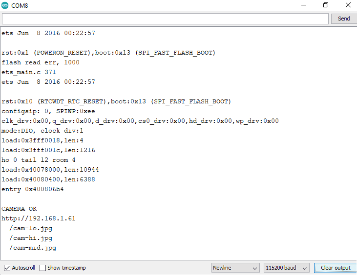
After successfully transmitting live video, ensure that you note down the displayed IP address.
Installation of Python Libraries
To view the live video stream on your computer, you need to write a Python script that retrieves video frames. The first step is to install Python. Visit python.org and download Python.
Install Python after downloading it. Next, open the command prompt and install the following libraries: NumPy, OpenCV, and pyzbar.
Type “pip install numpy” in the command prompt and press enter. Once the installation is complete, type “pip install opencv-python” and press enter. Finally, type “pip install pyzbar” and press enter. Close the command prompt once the installations are complete.
Python Code + QR Code Scanner ESP32 CAM
Open Idle code editor or any other Python code editor.
Create a new folder, and within the folder, create a new Python file and copy-paste the code provided below.
import cv2
import numpy as np
import pyzbar.pyzbar as pyzbar
import urllib.request

#cap = cv2.VideoCapture(0)
font = cv2.FONT_HERSHEY_PLAIN

url='http://192.168.1.61/'
cv2.namedWindow("live transmission", cv2.WINDOW_AUTOSIZE)

prev=""
pres=""
while True:
    img_resp=urllib.request.urlopen(url+'cam-hi.jpg')
    imgnp=np.array(bytearray(img_resp.read()),dtype=np.uint8)
    frame=cv2.imdecode(imgnp,-1)
    #_, frame = cap.read()

    decodedObjects = pyzbar.decode(frame)
    for obj in decodedObjects:
        pres=obj.data
        if prev == pres:
            pass
        else:
            print("Type:",obj.type)
            print("Data: ",obj.data)
            prev=pres
        cv2.putText(frame, str(obj.data), (50, 50), font, 2,
                    (255, 0, 0), 3)

    cv2.imshow("live transmission", frame)

    key = cv2.waitKey(1)
    if key == 27:
        break

cv2.destroyAllWindows()
Update the URL variable with the IP address copied from the Arduino Serial Monitor in the above code. Save the code and execute it.
Note: If you encounter issues with the pyzbar library, download Microsoft Visual C++ 2013 Redistributable (x64) – 12.0.30501 from here.
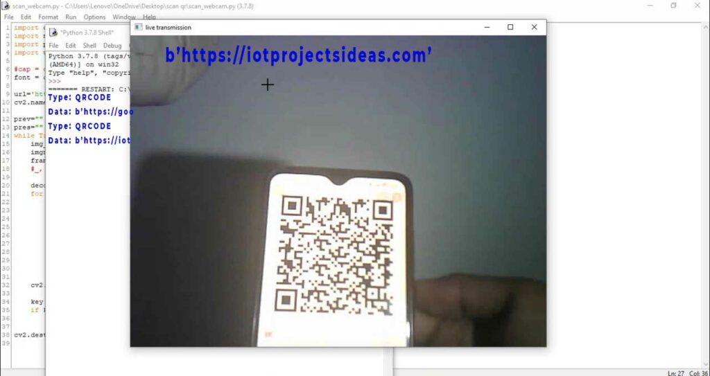
To test the project’s functionality, hold some QR Codes in front of the ESP32 CAM module. The computer screen displays the QR Code details, as shown in the image below.
Conclusion
So, that’s all for this tutorial. Following the above steps, you can create your own QR Code Scanner or Reader using ESP32 CAM Module and OpenCV Python libraries. If you have any doubts or queries then do let me know in the comment section below.
