Multiple LoRa Nodes Communication with Master LoRa Node
LoRa Two Way Communication with Multiple Nodes
Today in this tutorial, we will learn to make Multiple LoRa Nodes communication with the Master LoRa Node. But, before getting started with this tutorial, let’s have a quick overview of our previous Arduino and SX1278 LoRa transceiver modules.
- Quick Overview of Previous LoRa SX1278 based Projects
- Overview: Multiple LoRa Nodes Communication with Master LoRa Node
- Working of Multiple LoRa Nodes Communication
- Components Required
- Circuit Diagram of Multiple LoRa Communication
- Arduino Multiple LoRa Nodes Programming:
- LoRa Nodes Codes Explanation:
- Conclusion
Quick Overview of Previous LoRa SX1278 based Projects
In the first tutorial, I explained the maximum basic things including the SX1278 LoRa module Pinout, technical specifications, and its interfacing with the Arduino. I demonstrated a simple LoRa one-way communication project. It was an agriculture monitoring and automatic irrigation system. In which I monitored multiple sensors like soil moisture sensor, DS18B20 temperature sensor, and DHT22 Temperature & Humidity sensor remotely using LoRa SX1278 module on Blynk IoT Platform.
Then I made a long-range LoRa wireless two-way communication system using the same 433Mhz SX1278 LoRaTransceiver modules. In this project, I interfaced DHT22 sensor and 16×2 I2C LCD on the first LoRa Node. While on the second LoRa node I interface the DS18B20 temperature sensor and OLED Display.
Here I was simply sending the DHT22 temperature and humidity value from the First Node to the Second Node and then I was printing those values on the I2C OLED display module. While on the other side I used a DS18B20 temperature sensor and I was able to send the temperature value to the first node and then print its value on a 16×2 i2c LCD display. You can easily modify this project to monitor multiple sensors and control multiple devices as per your requirement.
Overview: Multiple LoRa Nodes Communication with Master LoRa Node
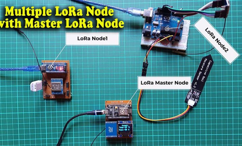
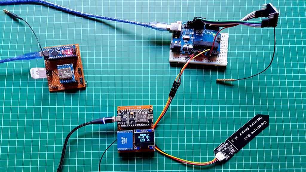
In today’s tutorial, you will learn how to perform Multiple LoRa Nodes Communication with the Master Lora Node. Here, I have three LoRa modules, you can use more if you have. So, in this demonstration, I am using one as the Master LoRa node and the other two as the LoRa end devices.
To the LoRa Node1, a capacitive soil moisture sensor is connected which I am going to use to measure the Relative Humidity of soil. But, you can replace this sensor with any other sensor of your requirement. In a LoRa Node2, the DHT22 temperature & humidity sensor is connected.
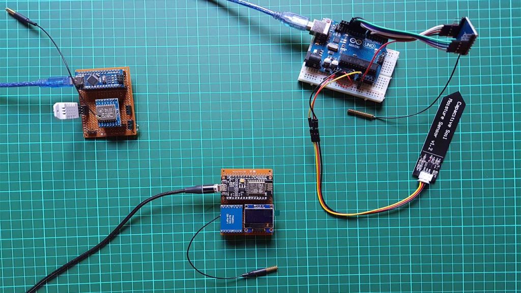
To the master LoRa Node, a 0.96 inch i2c supported Oled display module is connected which is used for displaying the data received from the other two LoRa end devices. So, you can see it in the image below. I have connected two different sensors to the Arduino LoRa nodes or LoRa end devices. We will send those sensor values to the master LoRa Node and print them on OLED Display along with the Node1 or Node2 information. You can add multiple LoRa Nodes with different sensors connected. So, let’s go ahead and check how this system works.
Working of Multiple LoRa Nodes Communication
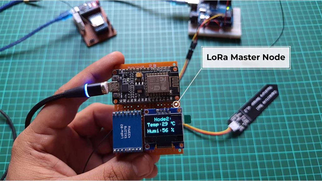
Here, Master LoRa Node sends a request to the LoRa end devices. For this, I created a timer using the millis() function. So, for the first 5 seconds, the Master LoRa node sends multiple requests to the LoRa Node1 and receives Soil Moisture Sensor data from the LoRa Node1. Then for the next 5 seconds, it receives temperature and humidity data from the LoRa Node2. You can change this time duration in the program code.
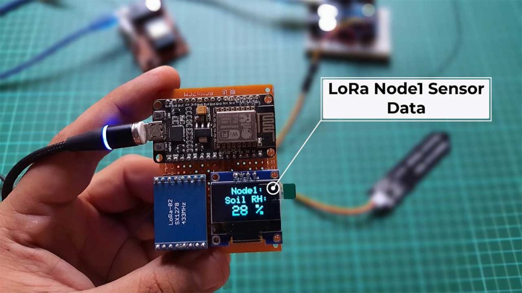
Those received sensor data from LoRa Nodes are printed on OLED Display Module. On the top of the Display, the Node name is printed. So you won’t have any confusion about from which node you are receiving data. This entire system is based on two-way communication. Thus you can also send commands to remote LoRa nodes to control devices.
You can DIY your own LoRaWAN project by converting this Master Node to LoRa Gateway. This is the main reason for using the NodeMCU ESP8266 12E Board on Master Node instead of the Arduino board. Because, using the nodemcu ESP8266 board I can easily send sensor data to IoT platforms like Thingspeak, Blynk IoT, Arduino IoT Cloud, Ubidots, AWS IoT, etc. It’s totally up to you how you modify and for what purpose you use this project. So, I hope you already got an idea of what you are going to learn here.
Components Required
All the components required for making Multiple LoRa Nodes Communication with Master LoRa Node are provided below. You can purchase all the components online from Amazon.
| S.N | Components Name | Quantity | |
|---|---|---|---|
| 1 | NodeMCU ESP8266-12E Board | 1 | https://amzn.to/3sCrEbj |
| 2 | Capacitive Soil Moisture Sensor | 1 | https://amzn.to/3nyL9y7 |
| 3 | DHT22 Temperature & Humidity Sensor | 1 | https://amzn.to/32VEw1X |
| 4 | 0.96" I2C OLED Display | 1 | https://amzn.to/3kvENyc |
| 5 | Arduino Nano | 2 | https://amzn.to/3Hf7zvN |
| 6 | LoRa SX1278 Transceiver Module | 3 | https://amzn.to/3G6xapO |
| 7 | Few jumpers wires | 20 | https://amzn.to/3klh0A4 |
*Please Note: These are affiliate links. I may make a commission if you buy the components through these links. I would appreciate your support in this way!
Circuit Diagram of Multiple LoRa Communication
Now, let us see how we can connect Multiple LoRa Nodes with Master LoRa Node. The circuit diagram and explanation of each LoRa node are provided below.
Master LoRa Node Circuit:
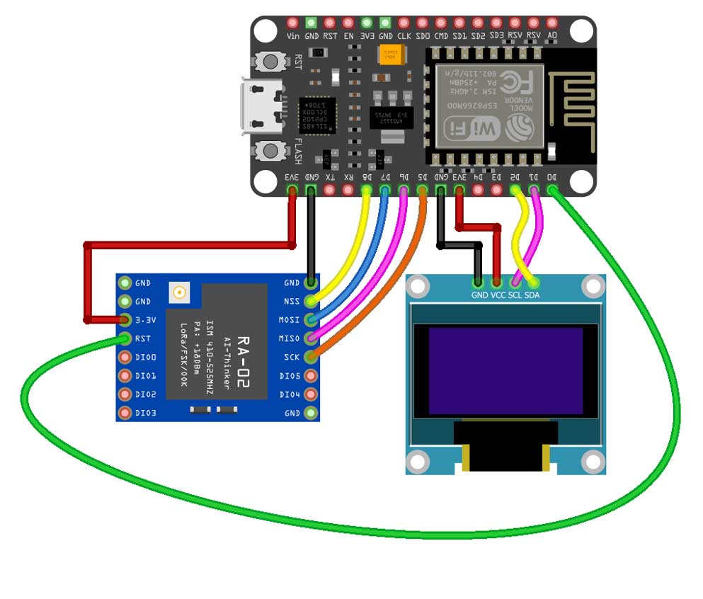
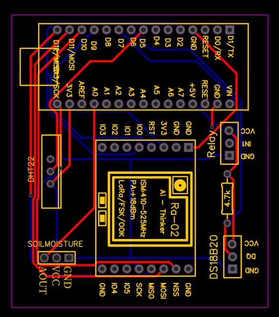
This is the circuit diagram of the Master LoRa Node. The VCC of the SX1278 Lora module is connected with the 3.3V of the NodeMCU. The MISO Pin of the LoRa module is connected with the NodeMCU pin D6. The MOSI pin is connected with the NodeMCU pin D7. The SCK pin of the LoRa module is connected with NodeMCU pin D5. The NSS pin is connected with pin D8 and the ground pin of the LoRa module is connected with the NodeMCU GND. The VCC and GND pins of the SSD1306 Oled display module are connected with the NodeMCU 3.3V and GND pins. The SDA and SCL pins of the Oled display module are connected with the NodeMCU I2C pins D1 and D2.
Arduino LoRa Node1 Circuit:
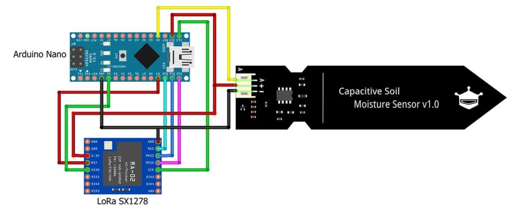
This is the circuit diagram of the LoRa Node1. The connection of the SX1278 Lora module, and Capacitive Soil Moisture Sensor remains exactly as shown here. The VCC of the LoRa module is connected with the 3.3V of the Arduino. The MISO Pin of the LoRa module is connected with Arduino’s pin 12. The MOSI pin is connected with the Arduino’s pin 11. The SCK pin of the LoRa module is connected with Arduino’s pin 13. The NSS pin is connected with the Arduino’s pin 10 and the ground pin of the LoRa module is connected with the Arduino’s GND.
The data wire (yellow) of the capacitive soil moisture sensor is connected with Analog pin A0 while the other two Red and Black wire of the soil moisture sensor is connected with the Arduino’s 3.3V and GND.
Arduino LoRa Node2 Circuit:
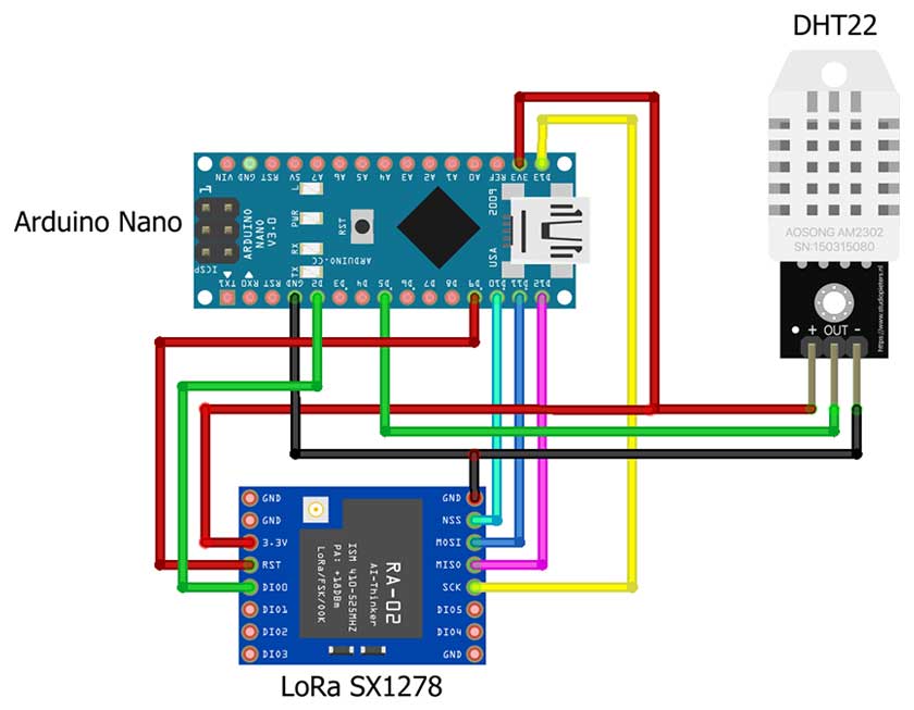
This is the circuit diagram of the LoRa Node2. The connection of the SX1278 Lora module remains exactly the same as LoRa Node1.
Out pin of the DHT22 sensor is connected to the D5 pin of the Arduino. Whereas VCC and GND are connected to 3.3V and GND pins of Arduino respectively.
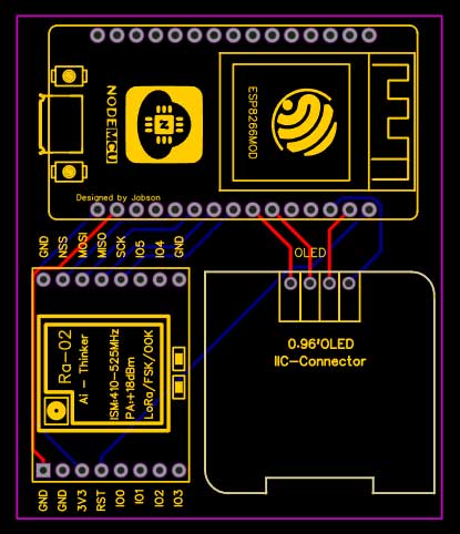
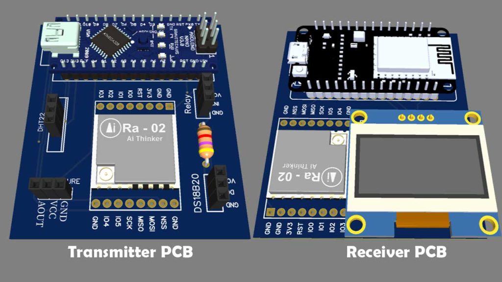
Project PCB Gerber File & PCB Ordering Online
You can simply assemble the circuit on a breadboard. But To remove messy wiring and give a clean look, I designed a PCB prototype for this project. It is also helpful for troubleshooting without any errors. You can download the Gerber file of my PCB Design from the link attached below. The PCB looks like the image shown below.
I provided the Gerber File for Multiple LoRa Nodes Communication with Master LoRa Node PCB below.
You can simply download the Gerber File and order your custom PCB from PCBWay

Visit the PCBWay official website by clicking here: https://www.PCBWay.com/. Simply upload your Gerber File to the Website and place an order. I prefer PCBWay for ordering custom PCBs. PCBWay is a place that brings manufacturers and customers together. They have more than a decade of experience in this field of fabrication, prototyping, and assembling PCBs. PCBWay have proved their focus to their customers’ needs in terms of cost-effectiveness, delivery, and quality. And this can be proved by their outstanding customer reviews.
Arduino Multiple LoRa Nodes Programming:
Before you start programming, first of all, make sure you download and install all the necessary library files.
As this project is based on multiple LoRa Nodes. Therefore, each LoRa Node has its own code. In this demonstration, we have three LoRa nodes. So, we will have three different codes. First, let’s start with the Master LoRa node.
Master LoRa Node Program Code:
/*
  Master Lora Node
  The IoT Projects

*/
#include <SPI.h>              // include libraries
#include <LoRa.h>
#include <Adafruit_GFX.h>
#include <Adafruit_SSD1306.h>

#define ss 15  //GPIO 15
#define rst 16  //GPIO 16
#define dio0 4  //GPIO 4

#define SCREEN_WIDTH 128 // OLED display width, in pixels
#define SCREEN_HEIGHT 64 // OLED display height, in pixels
// Declaration for an SSD1306 display connected to I2C (SDA, SCL pins)
#define OLED_RESET     -1 // Reset pin # (or -1 if sharing Arduino reset pin)
Adafruit_SSD1306 display(SCREEN_WIDTH, SCREEN_HEIGHT, &Wire, OLED_RESET);

byte MasterNode = 0xFF;
byte Node1 = 0xBB;
byte Node2 = 0xCC;

String SenderNode = "";
String outgoing;              // outgoing message

byte msgCount = 0;            // count of outgoing messages
String incoming = "";

// Tracks the time since last event fired
unsigned long previousMillis = 0;
unsigned long int previoussecs = 0;
unsigned long int currentsecs = 0;
unsigned long currentMillis = 0;
int interval = 1 ; // updated every 1 second
int Secs = 0;

int temperature;
int humidity;
int soilmoisturepercent;
int soilMoistureValue;

void setup() {
  Serial.begin(115200);                   // initialize serial
  display.begin(SSD1306_SWITCHCAPVCC, 0x3C);
  delay(500);
  display.clearDisplay();
  display.setTextColor(WHITE);

  while (!Serial);

  Serial.println("LoRa Master Node");

  LoRa.setPins(ss, rst, dio0);

  if (!LoRa.begin(433E6)) {
    Serial.println("Starting LoRa failed!");
    while (1);
  }
}

void loop() {


  currentMillis = millis();
  currentsecs = currentMillis / 1000;
  if ((unsigned long)(currentsecs - previoussecs) >= interval) {
    Secs = Secs + 1;
    //Serial.println(Secs);
    if ( Secs >= 11 )
    {
      Secs = 0;
    }
    if ( (Secs >= 1) && (Secs <= 5) )
    {

      String message = "10";
      sendMessage(message, MasterNode, Node1);
    }

    if ( (Secs >= 6 ) && (Secs <= 10))
    {

      String message = "20";
      sendMessage(message, MasterNode, Node2);
    }

    previoussecs = currentsecs;
  }

  // parse for a packet, and call onReceive with the result:
  onReceive(LoRa.parsePacket());

}


void sendMessage(String outgoing, byte MasterNode, byte otherNode) {
  LoRa.beginPacket();                   // start packet
  LoRa.write(otherNode);              // add destination address
  LoRa.write(MasterNode);             // add sender address
  LoRa.write(msgCount);                 // add message ID
  LoRa.write(outgoing.length());        // add payload length
  LoRa.print(outgoing);                 // add payload
  LoRa.endPacket();                     // finish packet and send it
  msgCount++;                           // increment message ID
}

void onReceive(int packetSize) {
  if (packetSize == 0) return;          // if there's no packet, return

  // read packet header bytes:
  int recipient = LoRa.read();          // recipient address
  byte sender = LoRa.read();            // sender address
  if ( sender == 0XBB )
    SenderNode = "Node1:";
  if ( sender == 0XCC )
    SenderNode = "Node2:";
  byte incomingMsgId = LoRa.read();     // incoming msg ID
  byte incomingLength = LoRa.read();    // incoming msg length


  while (LoRa.available()) {
    incoming += (char)LoRa.read();
  }

  if (incomingLength != incoming.length()) {   // check length for error
    //Serial.println("error: message length does not match length");
    ;
    return;                             // skip rest of function
  }

  // if the recipient isn't this device or broadcast,
  if (recipient != Node1 && recipient != MasterNode) {
    // Serial.println("This message is not for me.");
    ;
    return;                             // skip rest of function
  }

  // if message is for this device, or broadcast, print details:
  //Serial.println("Received from: 0x" + String(sender, HEX));
  //Serial.println("Sent to: 0x" + String(recipient, HEX));
  //Serial.println("Message ID: " + String(incomingMsgId));
  // Serial.println("Message length: " + String(incomingLength));
  // Serial.println("Message: " + incoming);
  //Serial.println("RSSI: " + String(LoRa.packetRssi()));
  // Serial.println("Snr: " + String(LoRa.packetSnr()));
  // Serial.println();

  if ( sender == 0XCC )
  {
    String t = getValue(incoming, ',', 0); // Temperature
    String h = getValue(incoming, ',', 1); // Humidity

    temperature = t.toInt();
    humidity = h.toInt();
    incoming = "";
    //clear display
    display.clearDisplay();
    display.setTextSize(2);
    display.setCursor(30, 0);
    display.print(SenderNode);
    // display temperature
    display.setTextSize(2);
    display.setCursor(0, 20);
    display.print("Temp: ");
    display.setCursor(60, 20);
    display.print(temperature);
    display.print(" ");
    display.setTextSize(1);
    display.cp437(true);
    display.write(167);
    display.setTextSize(2);
    display.print("C");

    // display humidity
    display.setTextSize(2);
    display.setCursor(0, 45);
    display.print("Humi: ");
    display.setCursor(60, 45);
    display.print(humidity);
    display.print(" %");
  }

  if ( sender == 0XBB )
  {

    String v = getValue(incoming, ',', 0); // Soil Moisture Value
    String p = getValue(incoming, ',', 1); // Soil Moisture percentage

    soilMoistureValue = v.toInt();
    soilmoisturepercent = p.toInt();


    incoming = "";

    //clear display
    display.clearDisplay();

    display.setTextSize(2);
    display.setCursor(35, 0);
    display.print(SenderNode);

    display.setCursor(20, 20); //oled display
    display.setTextSize(2);
    display.println("Soil RH:");

    display.setCursor(35, 40); //oled display
    display.setTextSize(3);
    display.print(soilmoisturepercent);
    display.setCursor(70, 40);
    display.setTextSize(3);
    display.println(" %");
    display.display();
  }

  display.display();
}
String getValue(String data, char separator, int index)
{
  int found = 0;
  int strIndex[] = { 0, -1 };
  int maxIndex = data.length() - 1;

  for (int i = 0; i <= maxIndex && found <= index; i++) {
    if (data.charAt(i) == separator || i == maxIndex) {
      found++;
      strIndex[0] = strIndex[1] + 1;
      strIndex[1] = (i == maxIndex) ? i + 1 : i;
    }
  }
  return found > index ? data.substring(strIndex[0], strIndex[1]) : "";
}
Arduino LoRa Node1 Program Code:
/*
  Lora Node1
  The IoT Projects

*/
#include <SPI.h>              // include libraries
#include <LoRa.h>

#define ss 10
#define rst 9
#define dio0 2

String outgoing;              // outgoing message

byte msgCount = 0;            // count of outgoing messages
byte MasterNode = 0xFF;
byte Node1 = 0xBB;

int AirValue = 590;   //you need to replace this value with Value_1
int WaterValue = 300;  //you need to replace this value with Value_2
int SensorPin = A0;
int soilMoistureValue = 0;
int soilmoisturepercent = 0;

String Mymessage = "";

void setup() {
  Serial.begin(115200);                   // initialize serial


  while (!Serial);

  Serial.println("LoRa Node1");

  LoRa.setPins(ss, rst, dio0);

  if (!LoRa.begin(433E6)) {
    Serial.println("Starting LoRa failed!");
    while (1);
  }
}

void loop() {
  soilMoistureValue = analogRead(SensorPin);  //put Sensor insert into soil
  soilmoisturepercent = map(soilMoistureValue, AirValue, WaterValue, 0, 100);

  // parse for a packet, and call onReceive with the result:
  onReceive(LoRa.parsePacket());
}

void onReceive(int packetSize) {
  if (packetSize == 0) return;          // if there's no packet, return

  // read packet header bytes:
  int recipient = LoRa.read();          // recipient address
  byte sender = LoRa.read();            // sender address
  byte incomingMsgId = LoRa.read();     // incoming msg ID
  byte incomingLength = LoRa.read();    // incoming msg length

  String incoming = "";

  while (LoRa.available()) {
    incoming += (char)LoRa.read();
  }

  if (incomingLength != incoming.length()) {   // check length for error
    // Serial.println("error: message length does not match length");
    ;
    return;                             // skip rest of function
  }

  // if the recipient isn't this device or broadcast,
  if (recipient != Node1 && recipient != MasterNode) {
    //Serial.println("This message is not for me.");
    ;
    return;                             // skip rest of function
  }
  Serial.println(incoming);
  int Val = incoming.toInt();
  if (Val == 10)
  {
    Mymessage = Mymessage + soilMoistureValue + "," + soilmoisturepercent;
    sendMessage(Mymessage, MasterNode, Node1);
    delay(100);
    Mymessage = "";
  }

}
void sendMessage(String outgoing, byte MasterNode, byte Node1) {
  LoRa.beginPacket();                   // start packet
  LoRa.write(MasterNode);              // add destination address
  LoRa.write(Node1);             // add sender address
  LoRa.write(msgCount);                 // add message ID
  LoRa.write(outgoing.length());        // add payload length
  LoRa.print(outgoing);                 // add payload
  LoRa.endPacket();                     // finish packet and send it
  msgCount++;                           // increment message ID
}
Arduino LoRa Node1 Program Code:
/*
  Lora Node2
  The IoT Projects

*/
#include <SPI.h>              // include libraries
#include <LoRa.h>
#include <DHT.h>

#define DHTPIN 5          //pin where the dht22 is connected
DHT dht(DHTPIN, DHT22);
#define ss 10
#define rst 9
#define dio0 2

String outgoing;              // outgoing message

byte msgCount = 0;            // count of outgoing messages
byte MasterNode = 0xFF;
byte Node2 = 0xCC;

float temperature;
float humidity;

String Mymessage = "";
String incoming = "";

void setup() {
  Serial.begin(115200);                   // initialize serial
  dht.begin();


  while (!Serial);

  Serial.println("LoRa Node2");

  LoRa.setPins(ss, rst, dio0);

  if (!LoRa.begin(433E6)) {
    Serial.println("Starting LoRa failed!");
    while (1);
  }
}

void loop() {

  temperature = dht.readTemperature();
  humidity = dht.readHumidity();


  // parse for a packet, and call onReceive with the result:
  onReceive(LoRa.parsePacket());
}

void onReceive(int packetSize) {
  if (packetSize == 0) return;          // if there's no packet, return

  // read packet header bytes:
  int recipient = LoRa.read();          // recipient address
  byte sender = LoRa.read();            // sender address
  byte incomingMsgId = LoRa.read();     // incoming msg ID
  byte incomingLength = LoRa.read();    // incoming msg length

  String incoming = "";

  while (LoRa.available()) {
    incoming += (char)LoRa.read();
  }

  if (incomingLength != incoming.length()) {   // check length for error
    // Serial.println("error: message length does not match length");
    ;
    return;                             // skip rest of function
  }

  // if the recipient isn't this device or broadcast,
  if (recipient != Node2 && recipient != MasterNode) {
    //Serial.println("This message is not for me.");
    ;
    return;                             // skip rest of function
  }
  Serial.println(incoming);
  int Val = incoming.toInt();
  if (Val == 20)
  {
    Mymessage = Mymessage + temperature + "," + humidity;
    sendMessage(Mymessage, MasterNode, Node2);
    delay(100);
    Mymessage = "";
  }

}

void sendMessage(String outgoing, byte MasterNode, byte Node2) {
  LoRa.beginPacket();                   // start packet
  LoRa.write(MasterNode);              // add destination address
  LoRa.write(Node2);             // add sender address
  LoRa.write(msgCount);                 // add message ID
  LoRa.write(outgoing.length());        // add payload length
  LoRa.print(outgoing);                 // add payload
  LoRa.endPacket();                     // finish packet and send it
  msgCount++;                           // increment message ID
}
LoRa Nodes Codes Explanation:
A detailed explanation of the Multiple LoRa Nodes Communication with Master LoRa Node program code is done in this video.
Simply copy the code to your Arduino IDE and upload the code to the respective LoRa Nodes. Don’t forget to choose the right COM port from the tools menu.
Conclusion
So, this is how we connect multiple Lora Nodes with the Master Lora Node for wireless communication system using LoRa SX1278 Module and Arduino. I hope the tutorial was helpful for you. In upcoming projects, I will make a network in which the Master Node will request data from the multiple Slave Nodes and upload data to the IoT Platform. Till then stay happy, stay safe.

Bro plz make smart health monitoring system using node MCU and online website which can measure our heart beat,O2,body temperature and room temperature .
Hi,Thank you for sharing this impressive project, but i have question after reading article, that is i was wondering the “Node”, can i add infinite “Node” to the network? and how this LoRa network topology looks like? can i daisy chain these node? thx for reply, if you can pls mail me 😀 i’m dying to find the answer~
Hello ,
multi node lora topic
I would like to have a circuit with a soil moisture lora transmitter (nano card).
and another circuit with an ssd1306 which displays the soil humidity and a relay which sticks when the humidity is 80%.
possible (uno card) .
email: hohm.michel@free.fr
Hello all,
Hope all doing well.
I am building smart irrigation project, for that I have bought 3 Reyax RYLR998 Lora modules.
I have connected one node to ESP8266 and made it gateway, and other two nodes are connected to ESP8266 which are slave node.
Slave node collect sensor data and send to gateway send commands to each node to operate relays connected to it.
Unfortunately, it does not work when I use two slave node, it works for one node to other node only.
So how to implement it? I googled it, could not find satisfactory solution.
Could you please share docs/links which shows, how to implement multiple Reyax RYLR998 lora nodes?