Smart Home using DWIN HMI Display & Arduino
DIY Smart Home Controller with DWIN HMI Display
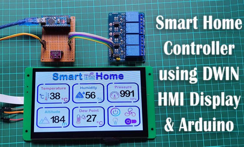
In this tutorial, we will make a Smart Home Controller using DWIN HMI Display and Arduino.
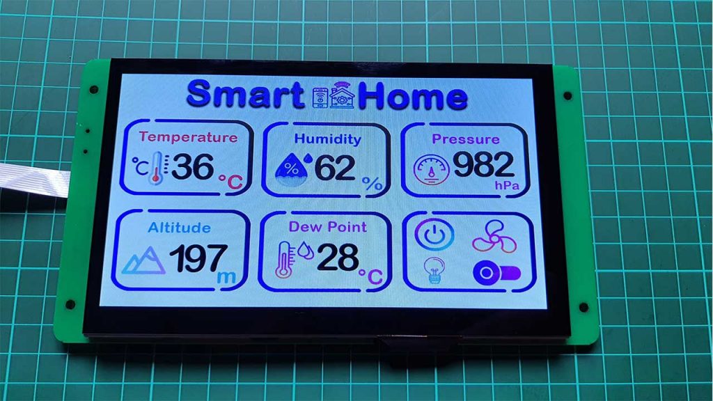
Here we will use the BME280 sensor to monitor Room Temperature, Room Humidity, Pressure, Approx Altitude, and DewPoint. Similarly, we will use four channel relay to control AC Home appliances like Lights, Fan, AC, TV, etc.
| S.N | Components Name | Quantity | Purchase Links |
|---|---|---|---|
| 1 | Arduino Nano board | 1 | https://amzn.to/3OnuHeB |
| 2 | 7-inch DWIN HMI Display | 1 | https://aliexpress.com/Dwin-Display |
| 3 | 8-Channel Relay Module | 1 | https://amzn.to/3HKpdLr |
| 4 | Jumper Wires | 20 | https://amzn.to/2JWSR44 |
| 5 | Breadboard | 1 | https://amzn.to/3n33uRT |
Overview: DWIN HMI Smart Home Project
I am using 7-inch DWIN HMI (DMG80480C070_04WTC) Display to monitor sensor data and control AC Home Appliances. If you are new to this HMI Display then there is a detailed getting started tutorial on the (DMG80480C070_04WTC) Display.

Today’s tutorial will be a bit longer because we will go through all the steps:
- Installing required Software & Tools
- Designing the GUI of Display
- Upload project files to the Display
- Interface sensor and relays to the Arduino
- Make a serial communication between Arduino & DWIN HMI Display.
- Monitor sensor data & Control AC Home appliances from this touch display.
7-inch DWIN HMI (DMG80480C070_04WTC) Display has a resolution of 800X480 pixels and can be easily used with 5V compatible microcontroller boards like Arduino Uno, Arduino Nano, Arduino Mega, PIC microcontrollers, 8051 family of microcontrollers, etc.
Install Required Software and tools
Now, let us visit the official website of DWIN Global dot com. You can see this DWIN company making a wide range of High-quality Touch screens for Android LCD, HDMI LCD, and Linux LCD Displays.
Under the Download, section Go to tools and Download the DGUS-DWIN Graphic utilized software i.e DGUS software and XR21X Driver. This driver is for HDL662B board. So, download and extract both files.
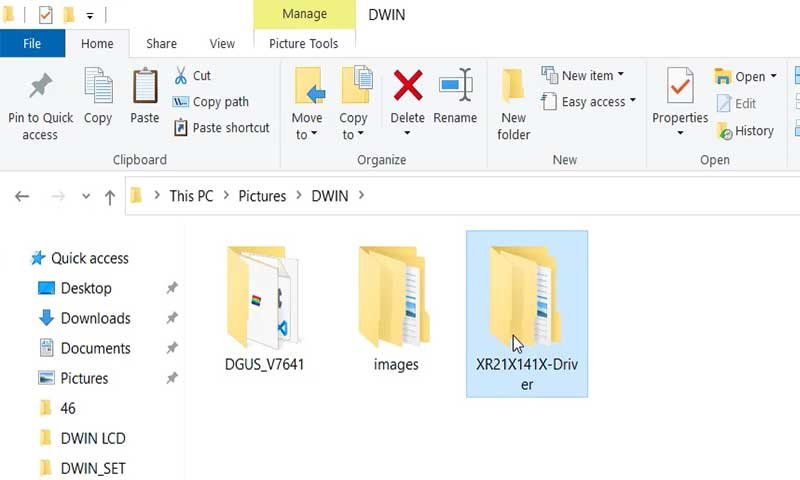
We don’t need to install this DGUS software. Under this DGUS folder, you can see some executables files. Which includes tools like the ICL tool, font generating tool, image resizing tool, etc. inside this DGUS Software.
Inside the XR21X folder, there are driver files. You need to install the driver on your PC to establish the communication between HDL662B and your PC. Double-click the executable file to launch the driver installer. Now click on Install to install the driver on your Windows PC.
GUI Designing
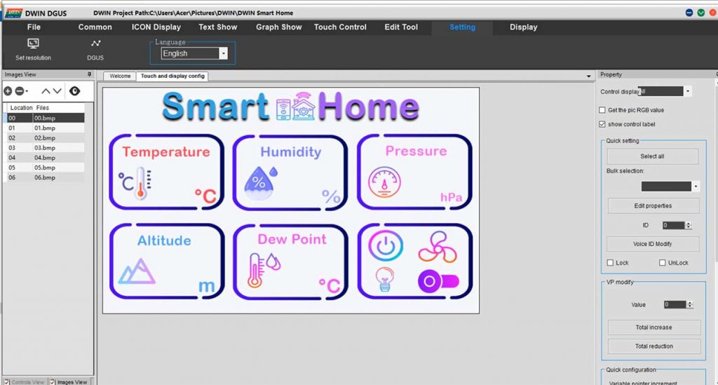
After installing the DGUS Software and driver. Open the DGUS.exe file. By default, the software language is Chinese. So, go to settings and change it to English.
Creating New project
Now click on New to create a new project. Select the screen resolution of 800×480 pixels. Choose your project folder path. In this demonstration, I am creating a new folder “DWIN Smart Home” and selecting the same folder path. Now you need to prepare images for your project. Here I have already created images and icons for my project.
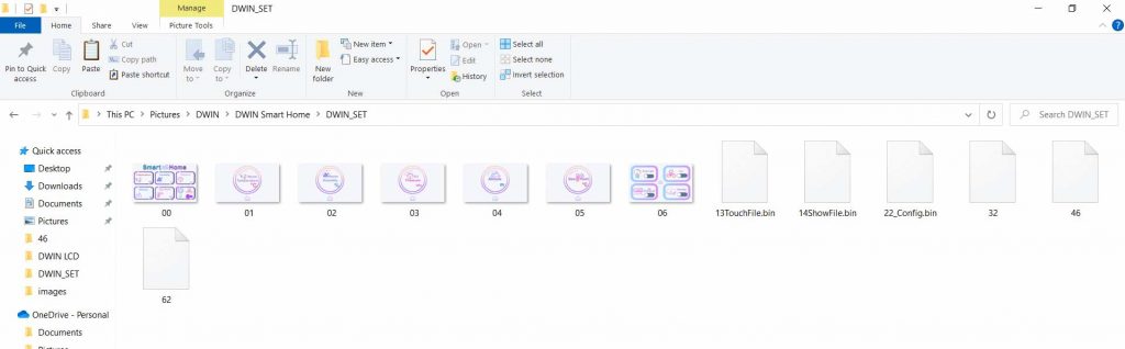
Note: You can name your images and icon folder as 32, 42, 46, 56, 58, 62, 64, etc. Because we need to create an ICL file of these pictures later and memory is divided into different sections.
Making Project Images and icons ready
In this tutorial Under 32 folder, I have placed images of my UI. Make sure that your images are in dot BMP format. Under the 46 folder, I have placed icon files. Similarly, on the 62 folder, I have placed number icon files.
Now, go back to DGUS and click on the welcome screen. Click on the picture conversion tool. On the top right corner set your screen resolution to 800×480 pixels. Now add your project images from the 32 folder. All the images inside that folder will be resized to 800×480 pixels. Here I have a total of 7 images. Click on the Image conversion option from the menu. Then select the images folder inside the “DWIN Smart Home” folder. So we have now converted all the images.
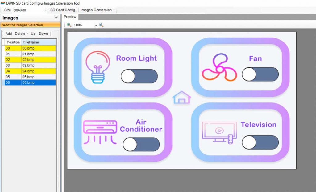
Now go to your project screen and add all those converted seven images.
Generate ICL File
We should create ICL files of our images. So, for that go to the settings menu and click on DGUS. A new window will pop up. Now click on ICL Tool. Here you need to select the images and generate an ICL file. Save this file with the name “32” under the DWIN_SET folder. Similarly, choose the button’s icon and generate ICL FIle as “46.icl” under the same DWIN_SET folder. Finally, select the number icons and generate the “62.icl” file under the same DWIN_SET folder.
We have successfully generated three ICL files. Now it’s time to add functions to our UI.
Adding Basic Touch Module
Here, select the “00.bmp” image then click on the “Touch Control” Menu. So, let’s create a basic touch module for our display. Click on the basic touch module then select the widget area where you want to apply this module. You can drag, drop and resize the module as your requirement. Now on the left side select the images for page switching. When we click on that touch module it will switch to a new assigned page.
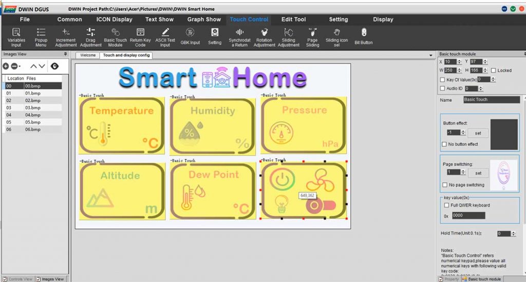
Now right-click on the newly created module and paste it 5 times. Drag one module for the Humidity widget and set the page switching to Humidity image. Similarly do the same for Pressure, Altitude, DewPoint, and Control settings. But don’t forget to change the page switching on every module.
So, we have created a basic touch module for our first image.
Adding Artistic Variable
Now Go to the ICON Display menu and create an Artistic Variable. Select the area and here you need to assign a VP address for this module. I’ am choosing 1000 as a VP address and selecting your icon file as 62. Now select the start icon as 0. Under the variable byte, choose integer 2 byte, and integer digits as 2. Set the initial value as zero.
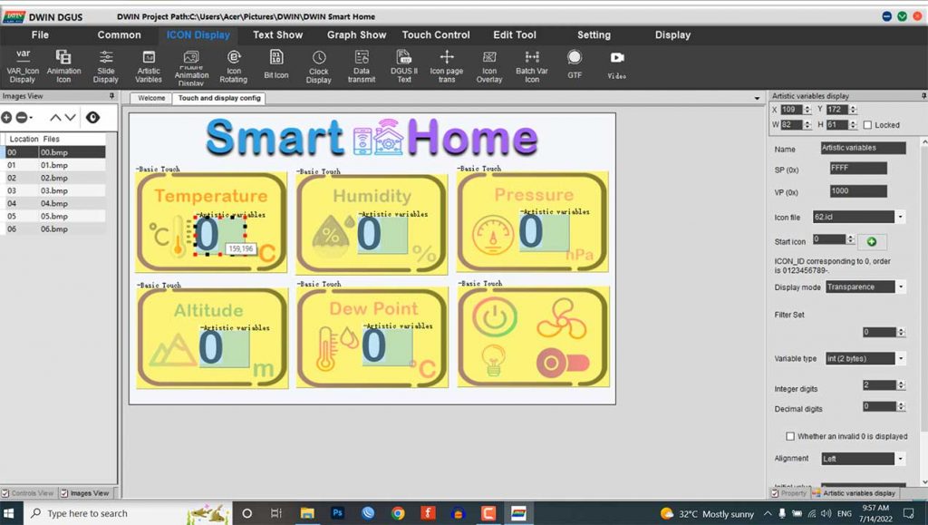
Note: You can set the initial number as the highest value of your sensor data and resize the artistic variable module according to your need and requirement.
Now copy this module and place them on humidity, pressure, altitude, and dewpoint. But don’t forget to change their VP address to 2000, 3000, 4000, and 5000 respectively. You can also change the variable type if required.
Copying Modules to different Images
Again copy the same module and paste it onto the 01.bmp image this one is for temperature. Resize and adjust the correct position as we did before.
Note: Keep the VP address 1000 for Temperature, 2000 for Humidity, 3000 for Pressure, 4000 for Altitude, and 5000 for DewPoint.
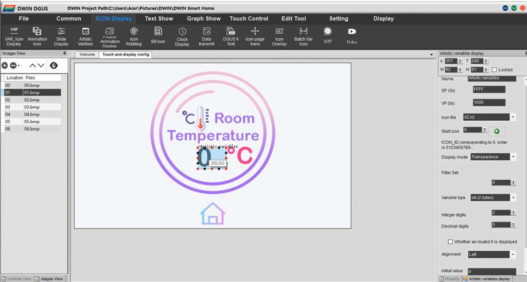
Copy this module and paste it on other images (02, 03, 04, 05) but change the VP address as we did here. Your VP address should match the VP address mentioned on the first image of our project.
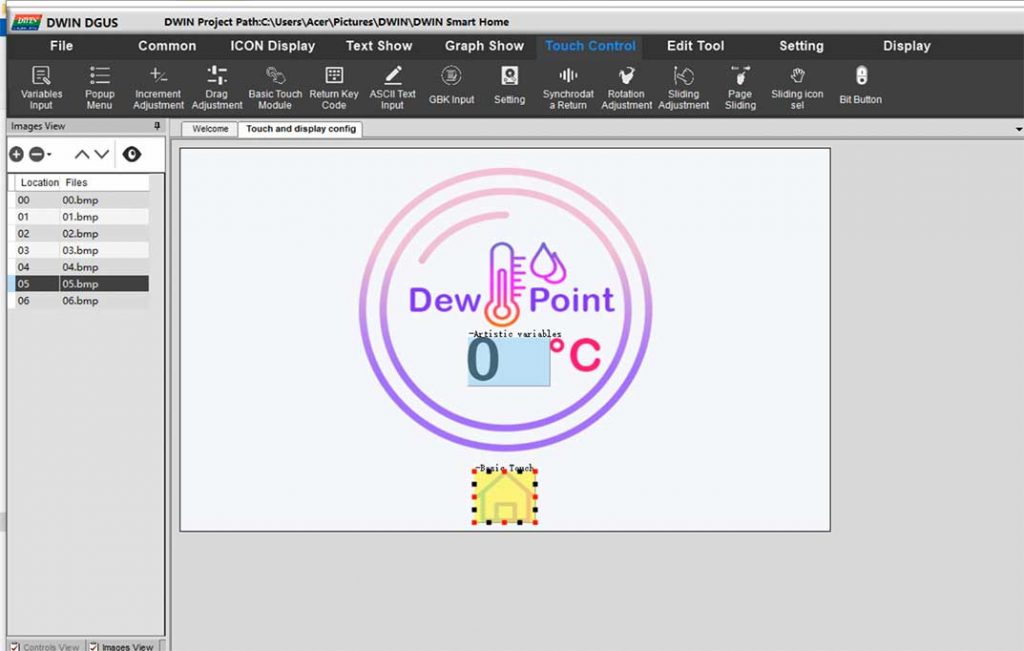
Again get back to the 01.bmp image and create a basic touch module for the home button. Select your page switching to the home page. Now again copy this module and paste it on every home button. You can always resize the module as per your requirements.
Configure Toggle Switch Design
Now let’s design our toggle switch buttons for controlling Appliances like lights, AC, Fan, TV, etc.
Go to ICON Display Menu and choose Var ICON Display. Select the area where you want to display your icon. As always resize the module as your needs. Now choose your VP address as 5100
Choose the icon ICL file as 46.icl. When the Value is Minimum select the OFF icon i.e zero icon. Similarly, set the maximum value as 1 and select the ON icon i.e one icon. Keep the display mode as transparence.
Now from the touch control menu select the increment adjustment module. You can resize the module. Then select data auto uploading. Click on the no-button effect. Give the same VP address as 5100. Click on Low Byte. Select the Adjust method as ++ and over limit operation as a cycle. Similarly, adjust step length to 1 and upper limit to 1. Finally, set the touch effect as a disposable setting.
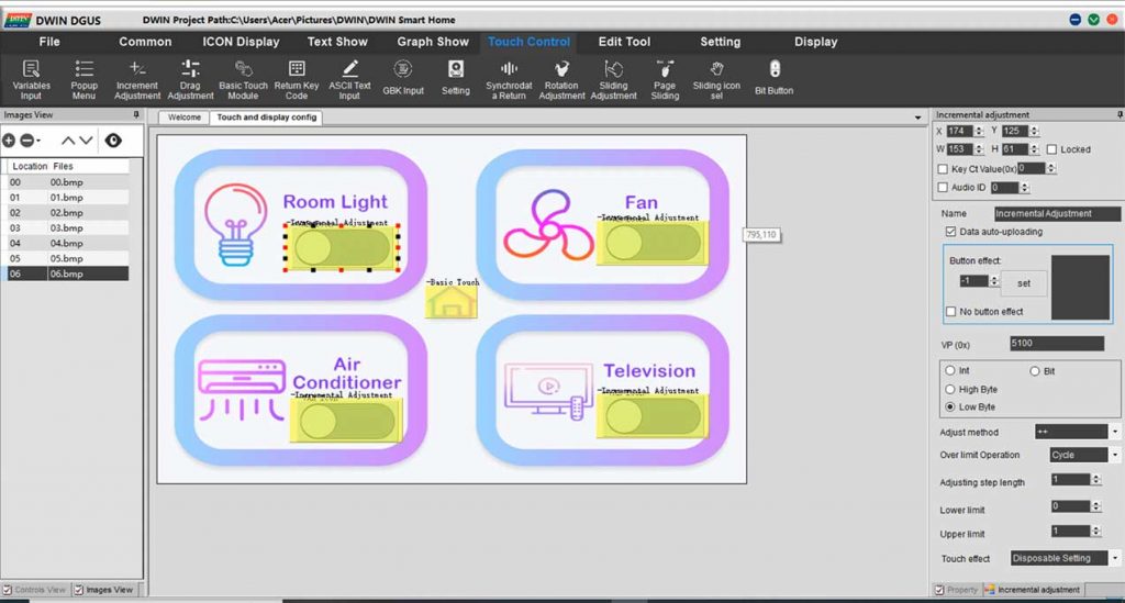
Now, copy the Var Icon module and paste them onto the Fan, AC, and TV controller buttons. But, change the VP address
For Light, the VP address is 5100, for Fan 5200, for AC 5300, and for TV 5400 respectively.
Also, copy and paste the incremental adjustment module and set their VP address accordingly.
Finally, we have completed adding modules to our UI. Now Click on Save and Generate, to generate 13 touch file, 14 show file, and 22 config bin files.
Preview of Newly Created GUI
Now you can preview the UI of our project from the display menu. Click on preview from the first page and you can see our newly created UI in a pop-up window.
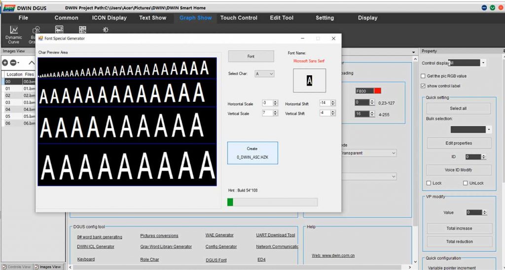
Here, we have not created a font file so let’s do it quickly. Go to the welcome page and click on word bank generating. Here choose your font and adjust your settings. Then click on create to create your font file. The font file will be created on the DGUS software folder by the name “0_DWIN_ASC.HZK” copy it and paste it into the DWIN_SET folder.
Now you can preview our new smart home UI. Here we cannot see the Artistic variable and button var icon module. They will be visible when we upload the project to our Display.
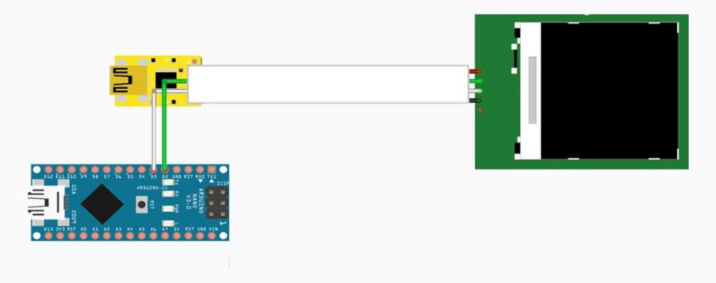
So let’s quickly do that. If you don’t know how to upload the project to this touch display then follow my previous getting started tutorial. In which I have explained two process to upload the project to your display using an SD card and T5L Download tool.
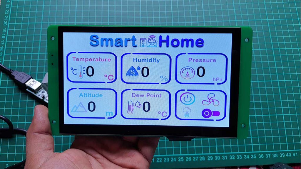
This is the result of our newly created UI After uploading the project file to the display.
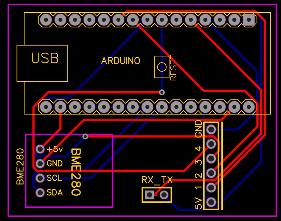
Circuit Diagram
After done with the GUI design you have to connect the BME280 sensor and Relay module to the Arduino board. You can use any 5V compatible Arduino board. Here I am using an Arduino Nano board. So, first, we interface the sensor and relays and make a serial communication to the display using RX2 and TX2 pins on the Display Module.
Note: If you are providing power from two different power sources to Arduino and LCD Separately then you need to connect the GND of Display to the GND Pin of Arduino.
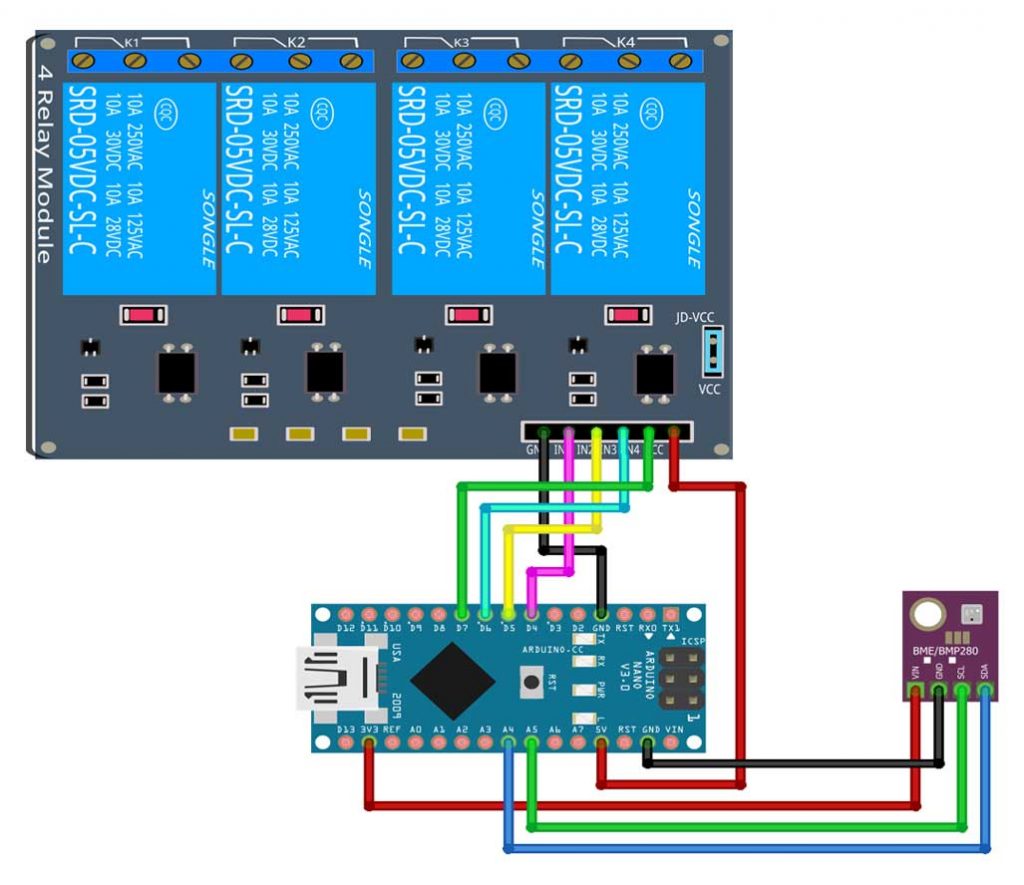
Connect the sensor, relay module, and DWIN HMI Display to the Arduino nano as shown in the image.
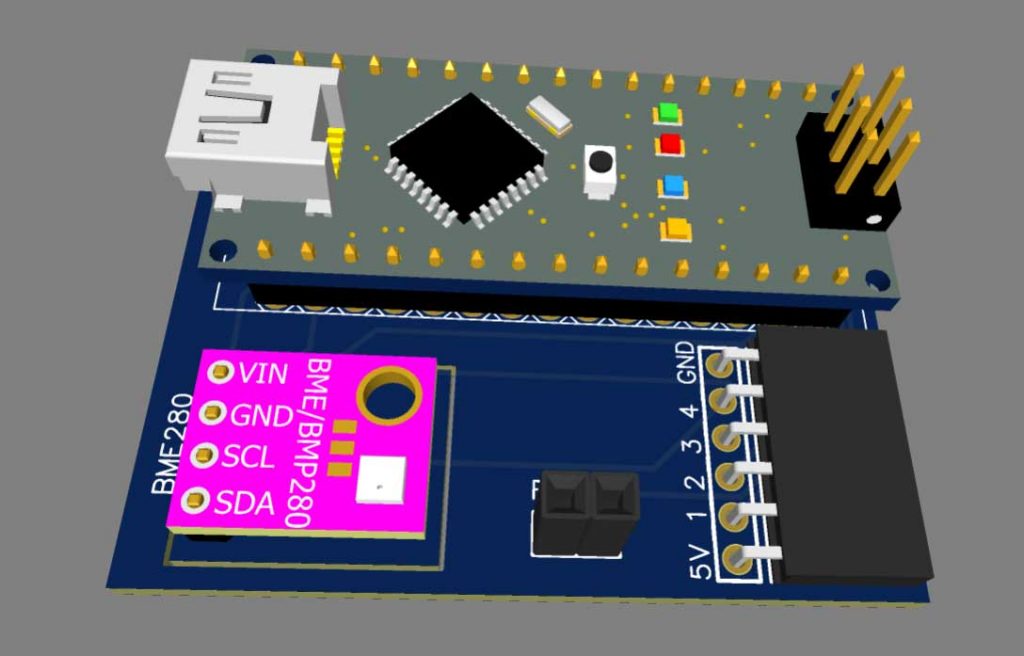
PCB Designing & Ordering Online
You can assemble this circuit on a breadboard as well but I prefer a custom PCB to avoid messy wiring. I Prefer to order a custom PCB from PCBWay.com
PCBWay.com is a one-stop solution for all your PCB needs like PCB prototyping, SMD stencils, PCB assembly, etc. currently, they are offering 10 pieces of 2 layered PCB at just 5 dollars.
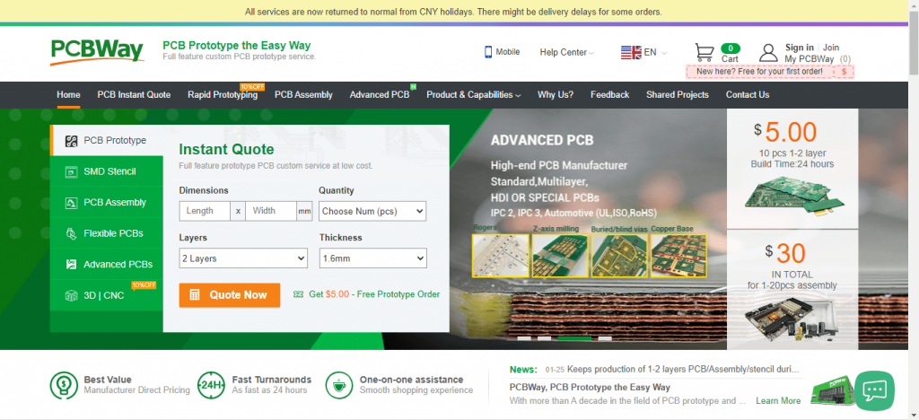
They also have a free signup bonus for new users. So, get your first prototype PCB ready from pcbway.com, the link is provided below.
Just click on the PCB Instant quote tab. Then click on Quick Order PCB. Now Upload your Gerber file and Place your order.
Program Code:
As in this project, we are sending as well as receiving data. For sending purpose, I am sending a frame with a VP address of that sensor and value, and that value is updating on Display. Similarly for receiving I am checking the serial receive frame for a particular button with their VP address using a switch case as you can see in the program code.
/* For Software serial */
#include <SoftwareSerial.h>
const byte rxPin = 2;
const byte txPin = 3;
SoftwareSerial mySerial (rxPin, txPin);
/* For BME280 sensor */
#include <Wire.h>
#include <Adafruit_Sensor.h>
#include <Adafruit_BME280.h>

#define SEALEVELPRESSURE_HPA (1013.25)
Adafruit_BME280 bme; // I2C
/* appliances pins */
int light = 4;
int fan = 5;
int ac = 6;
int tv = 7;
/* Adresses of all sensors */
unsigned char Buffer[9];
#define temperature_add   0x10
#define humidity_add     0x20
#define pressure_add   0x30
#define altitude_add     0x40
#define dewpoint_add     0x50
unsigned char   Temperature[8] = {0x5a, 0xa5, 0x05, 0x82, temperature_add , 0x00, 0x00, 0x00};
unsigned char      Humidity[8] = {0x5a, 0xa5, 0x05, 0x82, humidity_add, 0x00, 0x00, 0x00};
unsigned char   Pressure[8] = {0x5a, 0xa5, 0x05, 0x82, pressure_add , 0x00, 0x00, 0x00};
unsigned char      Altitude[8] = {0x5a, 0xa5, 0x05, 0x82, altitude_add, 0x00, 0x00, 0x00};
unsigned char      DewPoint[8] = {0x5a, 0xa5, 0x05, 0x82, dewpoint_add, 0x00, 0x00, 0x00};

void setup()
{
  Serial.begin(115200);
  mySerial.begin(115200);
  unsigned status;
  status = bme.begin();
  if (!status) {
    Serial.println("Could not find a valid BME280 sensor, check wiring, address, sensor ID!");
    while (1) delay(10);
  }
  pinMode(light, OUTPUT);
  digitalWrite(light, HIGH);
  pinMode(fan, OUTPUT);
  digitalWrite(fan, HIGH);
  pinMode(ac, OUTPUT);
  digitalWrite(ac, HIGH);
  pinMode(tv, OUTPUT);
  digitalWrite(tv, HIGH);
}
void loop()
{
  Data_Arduino_to_Display();
  delay(50);
  Data_Display_to_Arduino();
  delay(80);
}

void Data_Display_to_Arduino()
{
  if (mySerial.available())
  {
    for (int i = 0; i <= 8; i++) //this loop will store whole frame in buffer array.
    {
      Buffer[i] = mySerial.read();
    }

    if (Buffer[0] == 0X5A)
    {
      switch (Buffer[4])
      {
        case 0x51:   //for light
          if (Buffer[8] == 1)
          {
            digitalWrite(light, LOW);
          }
          else
          {
            digitalWrite(light, HIGH);
          }
          break;

        case 0x52:   //for fan
          if (Buffer[8] == 1)
          {
            digitalWrite(fan, LOW);
          }
          else
          {
            digitalWrite(fan, HIGH);
          }
          break;

        case 0x53:   //for AC
          if (Buffer[8] == 1)
          {
            digitalWrite(ac, LOW);
          }
          else
          {
            digitalWrite(ac, HIGH);
          }
          break;


        case 0x54:   //for TV
          if (Buffer[8] == 1)
          {
            digitalWrite(tv, LOW);
          }
          else
          {
            digitalWrite(tv, HIGH);
          }
          break;

        default:
          break;
      }
    }
  }
}

void Data_Arduino_to_Display()
{
  int t = bme.readTemperature();
  int h = bme.readHumidity();
  int p = bme.readPressure() / 100.0F;
  int a = bme.readAltitude(SEALEVELPRESSURE_HPA);
  int d = dewPointFast(t, h);
  /*------Print data to Serial Monitor------*/
    Serial.print("Temperature = ");
  Serial.print(t);
  Serial.println(" °C");

  Serial.print("Humidity = ");
  Serial.print(h);
  Serial.println(" %");

  Serial.print("Pressure = ");
  Serial.print(p);
  Serial.println(" hPa");

  Serial.print("Approx. Altitude = ");
  Serial.print(a);
  Serial.println(" m");

  Serial.print("DewPoint = ");
  Serial.print(d);
  Serial.println(" °C");
  Serial.println();

  Temperature[6] = highByte(t);
  Temperature[7] = lowByte(t);
  mySerial.write(Temperature, 8);
  Humidity[6] = highByte(h);
  Humidity[7] = lowByte(h);
  mySerial.write(Humidity, 8);
  Pressure[6] = highByte(p);
  Pressure[7] = lowByte(p);
  mySerial.write(Pressure, 8);
  Altitude[6] = highByte(a);
  Altitude[7] = lowByte(a);
  mySerial.write(Altitude, 8);
  DewPoint[6] = highByte(d);
  DewPoint[7] = lowByte(d);
  mySerial.write(DewPoint, 8);
}
/*----------DewPoint Calculation--------*/
double dewPointFast(double celsius, double humidity)
{
  double a = 17.271;
  double b = 237.7;
  double temp = (a * celsius) / (b + celsius) + log(humidity * 0.01);
  double Td = (b * temp) / (a - temp);
  return Td;
}
Arduino Code Explanation
In this program code, first, we include the library header file for the BME280 sensor.
/* For BME280 sensor */
#include <Wire.h>
#include <Adafruit_Sensor.h>
#include <Adafruit_BME280.h>
We defined the four relay pins assigned to the light, fan, AC, and TV.
/* appliances pins */
int light = 4;
int fan = 5;
int ac = 6;
int tv = 7;
Then we defined the VP address of BME280 sensor data like Temperature, Humidity, Pressure, Approx Altitude, and DewPoint.
/* appliances pins */
int light = 4;
int fan = 5;
int ac = 6;
int tv = 7;
This is the syntax of the frame which I am sending to the HMI-Display to display the sensor data.
unsigned char   Temperature[8] = {0x5a, 0xa5, 0x05, 0x82, temperature_add , 0x00, 0x00, 0x00};
unsigned char      Humidity[8] = {0x5a, 0xa5, 0x05, 0x82, humidity_add, 0x00, 0x00, 0x00};
unsigned char   Pressure[8] = {0x5a, 0xa5, 0x05, 0x82, pressure_add , 0x00, 0x00, 0x00};
unsigned char      Altitude[8] = {0x5a, 0xa5, 0x05, 0x82, altitude_add, 0x00, 0x00, 0x00};
unsigned char      DewPoint[8] = {0x5a, 0xa5, 0x05, 0x82, dewpoint_add, 0x00, 0x00, 0x00};
In the setup part, we initialized the serial monitor and my serial for serial communication. Then we initialize the bme280 sensor and relay output pins.
void setup()
{
  Serial.begin(115200);
  mySerial.begin(115200);
  unsigned status;
  status = bme.begin();
  if (!status) {
    Serial.println("Could not find a valid BME280 sensor, check wiring, address, sensor ID!");
    while (1) delay(10);
  }
  pinMode(light, OUTPUT);
  digitalWrite(light, HIGH);
  pinMode(fan, OUTPUT);
  digitalWrite(fan, HIGH);
  pinMode(ac, OUTPUT);
  digitalWrite(ac, HIGH);
  pinMode(tv, OUTPUT);
  digitalWrite(tv, HIGH);
}
In the loop, we run two custom functions to read values from the display and send sensor data to the display.
void loop()
{
  Data_Arduino_to_Display();
  delay(50);
  Data_Display_to_Arduino();
  delay(80);
}
In void data display to Arduino, we are receiving data from HMI-Display at the time of pressing any button.
void Data_Display_to_Arduino()
{
  if (mySerial.available())
  {
    for (int i = 0; i <= 8; i++) //this loop will store whole frame in buffer array.
    {
      Buffer[i] = mySerial.read();
    }

    if (Buffer[0] == 0X5A)
We have here four switch cases for Light, Fan, AC, and TV.
switch (Buffer[4])
      {
        case 0x51:   //for light
          if (Buffer[8] == 1)
          {
            digitalWrite(light, LOW);
          }
          else
          {
            digitalWrite(light, HIGH);
          }
          break;

        case 0x52:   //for fan
          if (Buffer[8] == 1)
          {
            digitalWrite(fan, LOW);
          }
          else
          {
            digitalWrite(fan, HIGH);
          }
          break;

        case 0x53:   //for AC
          if (Buffer[8] == 1)
          {
            digitalWrite(ac, LOW);
          }
          else
          {
            digitalWrite(ac, HIGH);
          }
          break;


        case 0x54:   //for TV
          if (Buffer[8] == 1)
          {
            digitalWrite(tv, LOW);
          }
          else
          {
            digitalWrite(tv, HIGH);
          }
          break;
Now here we get the sensor parameters like temperature, humidity, pressure, altitude, and dewpoint.
void Data_Arduino_to_Display()
{
  int t = bme.readTemperature();
  int h = bme.readHumidity();
  int p = bme.readPressure() / 100.0F;
  int a = bme.readAltitude(SEALEVELPRESSURE_HPA);
  int d = dewPointFast(t, h);
But the DewPoint is calculated using some mathematical expression.
/*----------DewPoint Calculation--------*/
double dewPointFast(double celsius, double humidity)
{
  double a = 17.271;
  double b = 237.7;
  double temp = (a * celsius) / (b + celsius) + log(humidity * 0.01);
  double Td = (b * temp) / (a - temp);
  return Td;
}
So Now, these data are printed on a serial monitor.
  /*------Print data to Serial Monitor------*/
    Serial.print("Temperature = ");
  Serial.print(t);
  Serial.println(" °C");

  Serial.print("Humidity = ");
  Serial.print(h);
  Serial.println(" %");

  Serial.print("Pressure = ");
  Serial.print(p);
  Serial.println(" hPa");

  Serial.print("Approx. Altitude = ");
  Serial.print(a);
  Serial.println(" m");

  Serial.print("DewPoint = ");
  Serial.print(d);
  Serial.println(" °C");
  Serial.println();
Using this syntax we also send sensor data to DWIN HMI Display through serial communication.
Temperature[6] = highByte(t);
  Temperature[7] = lowByte(t);
  mySerial.write(Temperature, 8);
  Humidity[6] = highByte(h);
  Humidity[7] = lowByte(h);
  mySerial.write(Humidity, 8);
  Pressure[6] = highByte(p);
  Pressure[7] = lowByte(p);
  mySerial.write(Pressure, 8);
  Altitude[6] = highByte(a);
  Altitude[7] = lowByte(a);
  mySerial.write(Altitude, 8);
  DewPoint[6] = highByte(d);
  DewPoint[7] = lowByte(d);
  mySerial.write(DewPoint, 8);
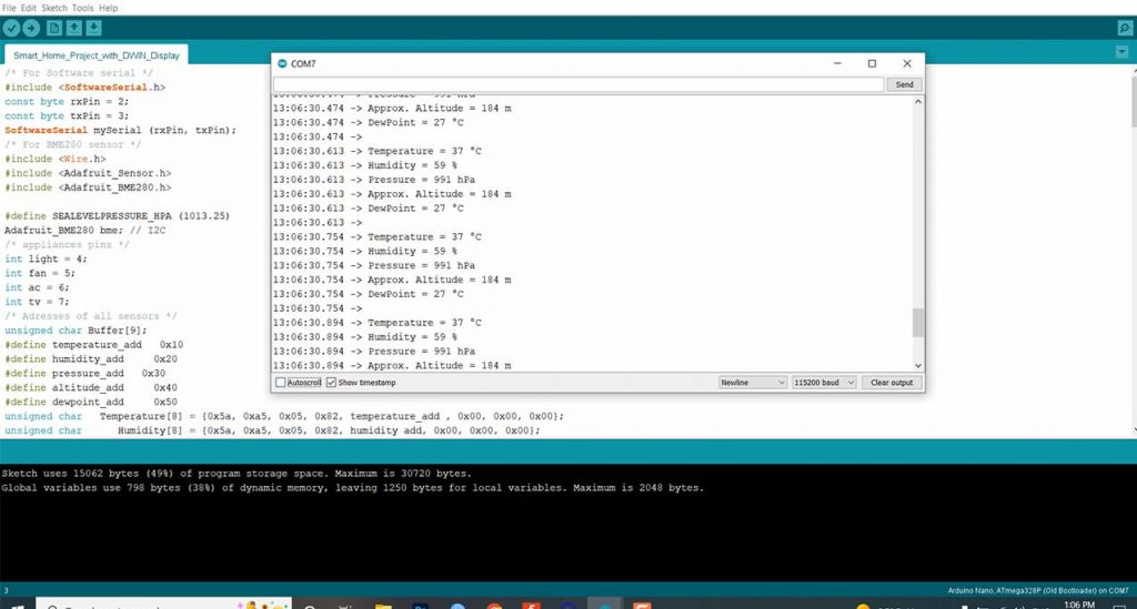
Uploading Program Code
Before uploading the program code you need to unplug the TX2 and RX2 pins from DWIN Display. Now Select your Arduino board and correct COM Port to upload this program into your Arduino.
Click on the upload button to upload the code. After successful upload of the program open the serial monitor at the baudrate of 115200 to see the real-time sensor data.
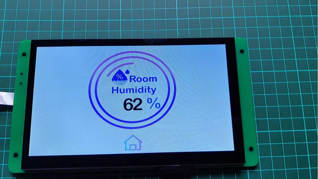
Demonstration:
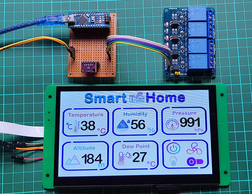
Now you can also see the real-time sensor data on a DWIN HMI Display. You can click on any widget to monitor the single data on a full 7-inch Display. You can press the home button to get back to the main dashboard.
By clicking on the control Widget, you can get to the control center to control your Appliances connected through this 4-channel relay.
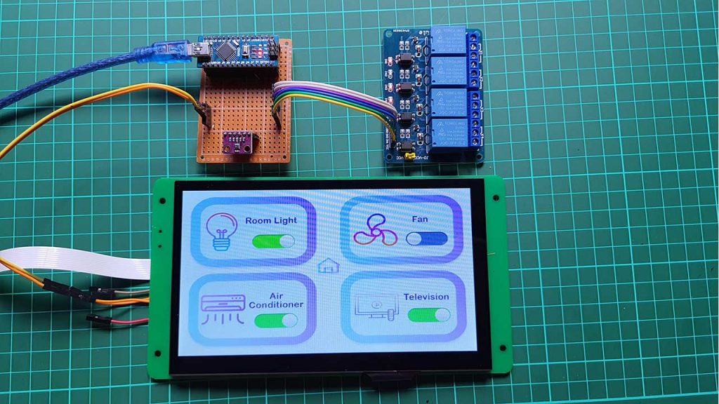
So, we have successfully made this Smart Home Controller Project with DWIN HMI Display and Arduino. The UI looks pretty good in this display.
I hope this tutorial was helpful to you. If it really helped you then don’t hesitate to like and share the project page with your friends.


Hi, thank you for sharing this project. Can you share Arduino .ino file and icon pictures instead of ICL files?
hi, good project, nice demo,
can u plz, share DWprj.hmi file.
thank u
Leonardo
I love the project
tôi không thể hiển thị nút nhấn và số trên màn DWIN nhưng lại hiện trong virtual, hãy giúp tôi