Home Automation using ESP32 & Blynk 2.0
ESP32 Smart Home Automation using Blynk 2.0
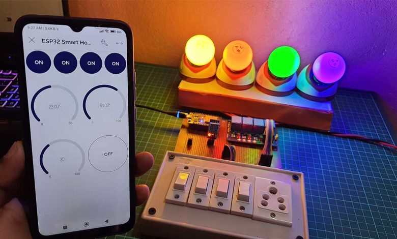
In this IoT project, we will make an IoT based home automation project using ESP32 and New Blynk 2.0 IoT Platform. Using Internet connectivity, we can control four appliances and monitor the sensor data using the Blynk IoT app from anywhere in the world. If there is no internet, you can still control the appliances with manual switches.
Overview: ESP32 Home Automation with Realtime Feedback
This project has a real-time feedback system in the new Blynk 2.0 IoT app and Blynk IoT Cloud Web Dashboard. The most important feature of this project is that ESP32 can also remember the last states of the relay. It will save the last GPIO States on ESP32 EEPROM. So after the power failure when ESP32 restarts, the appliances will automatically turn on according to the previous state of the relay.
If you see the blue LED glowing on ESP32 then it indicates that ESP32 is connected to your WiFi Network. So you can control the appliances remotely using Blynk IoT app or Blynk Cloud Web Dashboard.
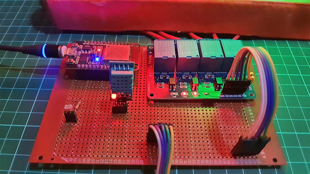
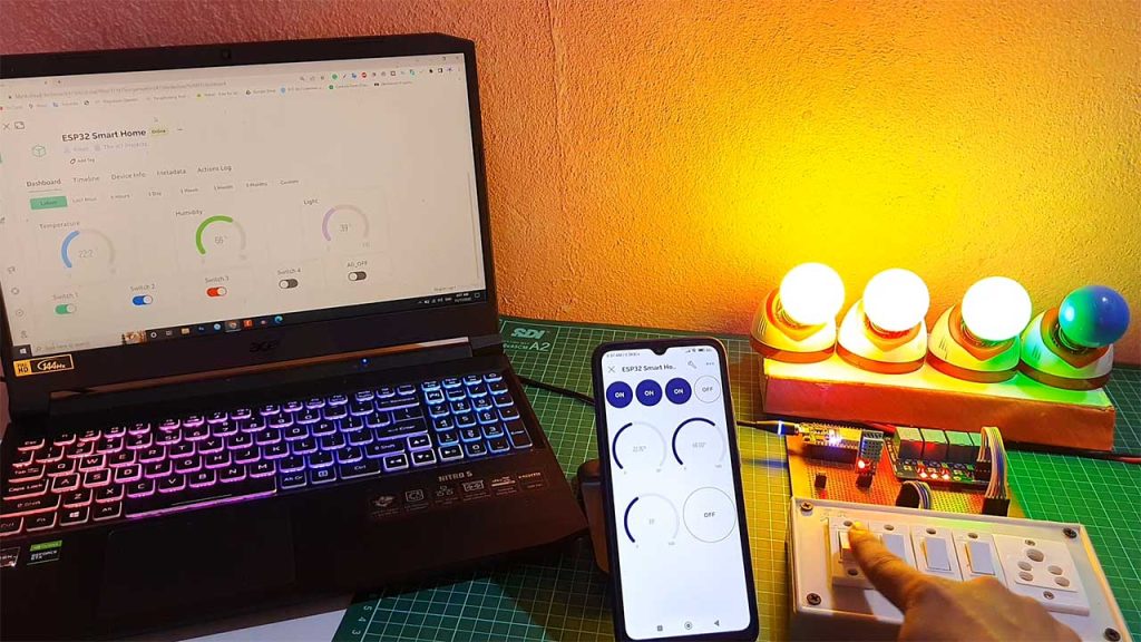
You can also use manual switches to control these lights. This projects works even when there is no internet connectivity. Now let me turn off the Wi-Fi and show you how it works without the internet. After turning off the Wi-Fi you can see the blue LED turn off. So I can only control these appliances using manual switches. let me turn on the Wi-Fi again. If Wi-Fi is available, the ESP32 will automatically connect with Wi-Fi and the blue LED will turn on. Now again I can control all these lights with Blynk IoT Platform.
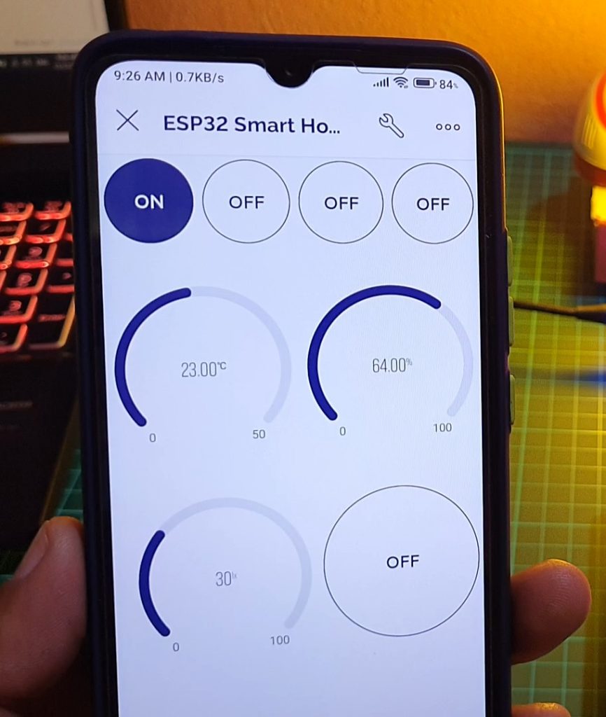
We are monitoring Temperature, Humidity, and Light intensity using DHT11 and LDR Sensor. You can clearly see the sensor data updated every second on both web dashboard and mobile application. So without further delay, let’s get started and see how we can implement this system.
Components Required
To make this IoT based Home Automation project, I have used a zero PCB board. You use a custom PCB or Breadboard for Assembly. ESP32 WiFi Module, LDR Sensor, DHT11 Sensor, 4 channel relay module, 4 Manual Switches, and 4 Lamps with Holder for testing this project. You can easily purchase all the components from amazon link provided below:
| S.N | Components Name | Quantity | |
|---|---|---|---|
| 1 | ESP32 DEV KIT | 1 | https://amzn.to/3OnuHeB |
| 2 | DHT22 Sensor | 1 | https://amzn.to/3cbRQnp |
| 3 | DHT11 Sensor | 1 | https://amzn.to/3CkDziN |
| 4 | LDR Sensor | 1 | https://amzn.to/3pAg3aa |
| 5 | 4-Channel Relay Module | 1 | https://amzn.to/3RP6ZLv |
| 6 | 10K ohm resistor | 1 | https://amzn.to/3K7xMiq |
| 7 | Jumper Wires | 10 | https://amzn.to/2JWSR44 |
| 8 | Breadboard | 1 | https://amzn.to/3n33uRT |
Circuit Diagram: ESP32 Home Automation
The circuit Diagram for Home Automation using Blynk 2.0 & ESP32 with Real-Time Feedback is very simple. let’s see the circuit diagram of this project.
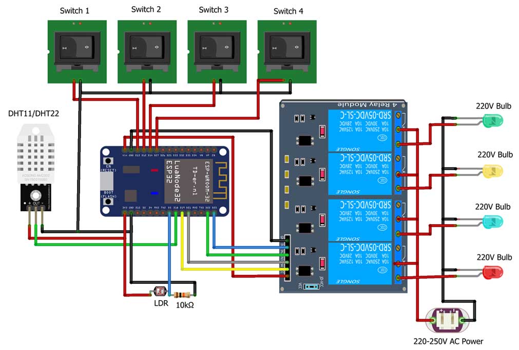
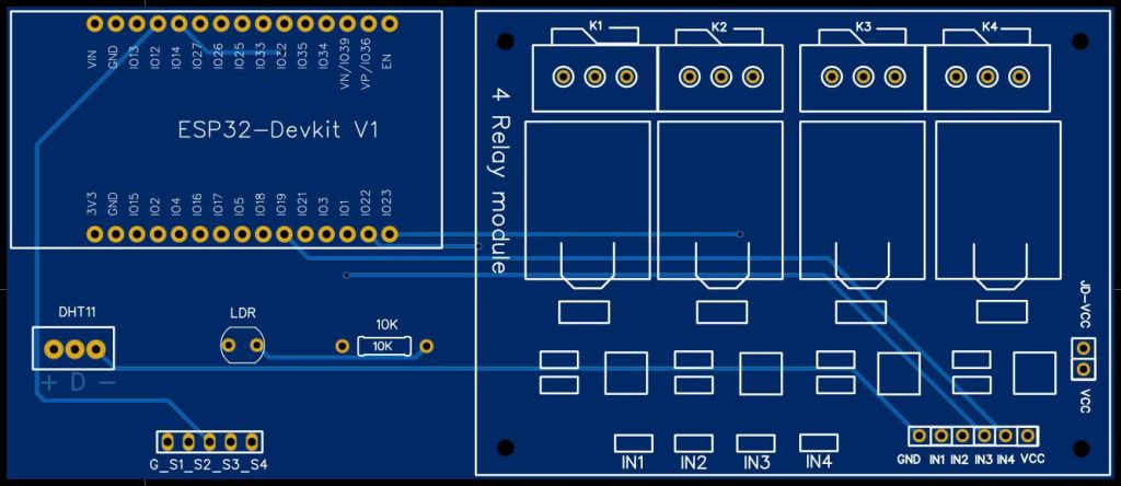
Four relays are connected to ESP32 GPIO 23 22 21 and 19 pins. Manual switches are connected to ESP32 GPIO 13 12 14 and 27. DHT11 and LDR sensors are connected to GPIO 18 and VN pins of ESP32 respectively. The Relay Module and ESP32 are powered through an external 5 volt power supply. Connect Four AC appliances at the output terminal of relay. Please take proper safety precautions while connecting these appliances with the relay module.
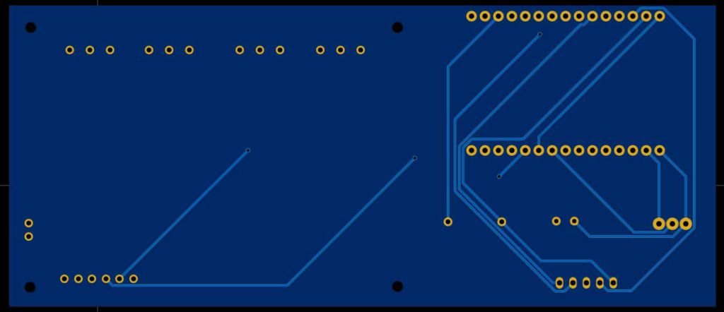
Project PCB Gerber File & PCB Ordering Online
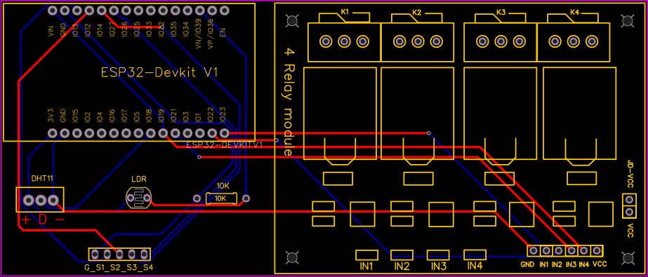
Now you can visit the PCBWay official website by clicking here: PCBWay.com. So you will be directed to the PCBWay website. Currently, PCBWay is celebrating their 10th Anniversary with amazing offers and special events! If you’re into electronics and PCB projects like me, you definitely don’t want to miss out on this.
PCBWay has been a trusted partner for PCB prototyping, manufacturing, and assembly for a decade now. To celebrate this milestone, they have a bunch of exciting deals and giveaways lined up. You can visit their special anniversary page at www.pcbway.com/activity/anniversary10th.html to participate.
I’ve been using PCBWay for my own projects, and their quality and customer service have always been top-notch. Whether you’re a hobbyist or a professional, PCBWay’s services are perfect for bringing your ideas to life.And during this anniversary celebration, they are offering discounts, free trials, and even a chance to win some fantastic prizes!
So, what are you waiting for? Head over to PCBWay.com and join in the celebration. Let’s make some great projects together. Thanks again to PCBWay for sponsoring this project.
Gerber file of this project is provided below.
- Just click on the PCB Instant quote tab.
- Then click on Quick Order PCB.
- Now Upload your Gerber file
- Select your preferred shipping method
- Place your order.
Setup Blynk 2.0 Web & Mobile Dashboard
Now let’s set up the Blynk Web Dashboard first. To do that visit blynk.io and sign up using the email ID.
Create a template
- Enter a template name. I am Giving it an “ESP32 Smart Home ”.
- Select the hardware board (ESP32).
- The connection type will be WiFi.
- You can add a description of your project if required.
- Click on Done.
- Now the template is created.
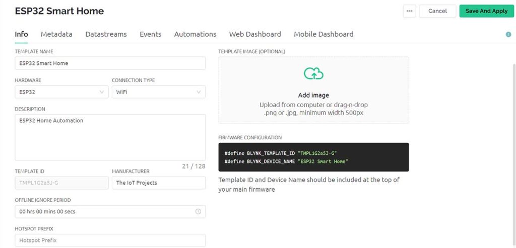
Creating New Blynk Datastreams
In our project, we are monitoring eight parameters. So you can give names to those parameters. In my case, Temperature, Humidity, Light, 4 switches, and all off switch are eight DataStream.
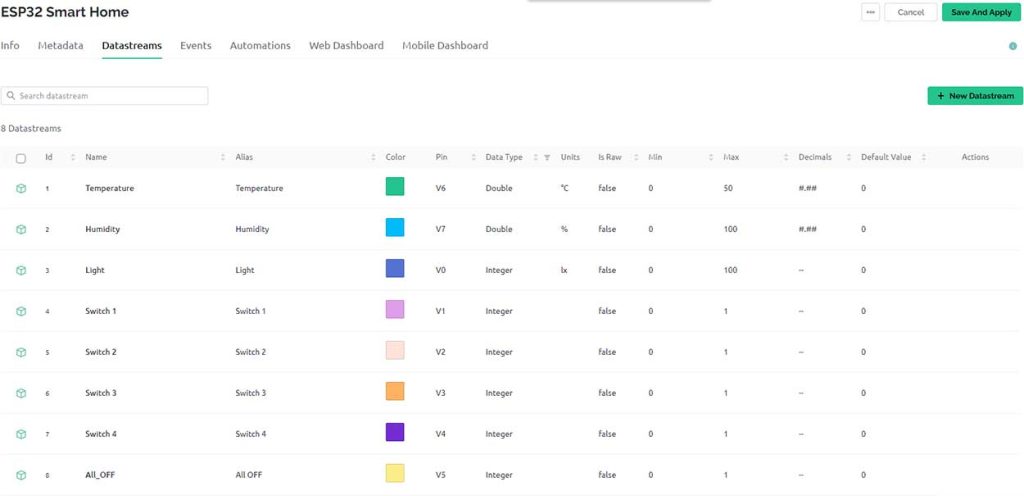
I have selected V0, to V7 respectively for our DataStreams for the Live Monitoring. The Variable data type is a integer for all the variables except Temperature and Humidity which is an Double Data type.
Design the Blynk 2.0 Web Dashboard
After that move on to the web dashboard. In this section, you will be able to see some widgets for making your cool-looking web dashboard. Now, simply add 3 Gauge widgets and 5 button widgets to your main screen. You need to configure them by providing a name and selecting datastream from the list. Click on Save and Apply to make changes to what setup has been made so far.
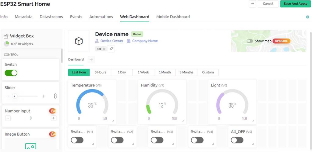
Now your Web Dashboard is Finally Ready. Using this Web Dashboard, you can control your Home Appliances.
Adding New Device
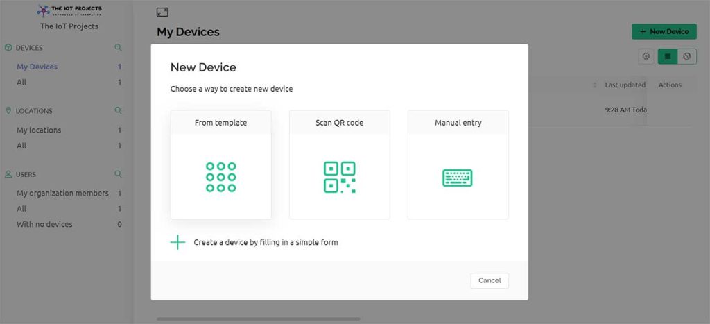
Lets Add a New Device. Select the first option, i.e. From Template. Choose your Template and give a Device Name then Click on Create.
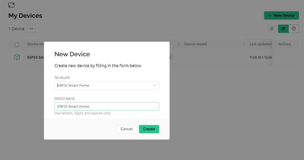
A New Device will be created. A snip of the code header file will appear on the Dashboard. Copy and save this code as it will be used in the Program code.
Setup Blynk IoT 2.0 Mobile Dashboard
Apart from the Web Dashboard, you can also set up your Mobile App Dashboard. For that download the Blynk IoT app from Playstore or AppStore. After installing the application login into your account. Turn on the developer mode if it is not turned on by going into your profile. You need to add 5 button switch widgets and 3 Gauge Widgets and configure their virtual datastreams. This step is very similar as we did on configuring web dashboard. You can follow the video below to set up the Dashboard if needed.
Furthermore, you can arrange and resize the widgets after which the Mobile App Dashboard looks something like this.

Code/Program: Blynk 2.0 Home Automation with ESP32
Before you start the programming, first of all, make sure you have downloaded all the necessary libraries.
You have to enter the Template ID, Device Name, and Authentication token. You can find them under device information.
/* Fill-in your Template ID Device Name and Auth Token */
#define BLYNK_TEMPLATE_ID "TMPL1G2a58-G"
#define BLYNK_DEVICE_NAME "ESP32 Smart Home"
#define BLYNK_AUTH_TOKEN "1gBzrgy1pgjLsMC7tuBNPODZxg_sFclJ"
Apart from these, update the WiFi SSID and Password from the following lines.
// Your WiFi credentials.
// Set password to "" for open networks.
char ssid[] = "IoT Projects Ideas";
char pass[] = "@1234567";
Now, if you followed the same circuit, then after doing all these changes, you can copy the code provided below and directly upload the code to ESP32. For that go to tools, select the board as DoIT ESP32 devkit V1, then select the proper port, and hit the upload button.
/**********************************************************************************
  Smart Home Automation using ESP32 with Blynk 2.0 with Real time feedback + EEPROM + No WiFi Control
  -----------------------
  Website: https://iotprojectsideas.com/

    Preferences--> Aditional boards Manager URLs :
    https://dl.espressif.com/dl/package_esp32_index.json, http://arduino.esp8266.com/stable/package_esp8266com_index.json

    Download Board ESP32 : https://github.com/espressif/arduino-esp32

    Download the libraries
    Blynk Library (1.1.0):  https://github.com/blynkkk/blynk-library
    DHT Library (1.4.3): https://github.com/adafruit/DHT-sensor-library
 **********************************************************************************/

/* Fill-in your Template ID Device Name and Auth Token */
#define BLYNK_TEMPLATE_ID "TMPL1G2a5J-G"
#define BLYNK_DEVICE_NAME "ESP32 Smart Home"
#define BLYNK_AUTH_TOKEN "1gBzrgy1pgjLsMCBtuBNPODZxg_sFclJ"

// Your WiFi credentials.
// Set password to "" for open networks.
char ssid[] = "IoT Projects Ideas";
char pass[] = "@1234567";


//#define BLYNK_PRINT Serial
#include <WiFi.h>
#include <WiFiClient.h>
#include <BlynkSimpleEsp32.h>
#include <Preferences.h>
#include <DHT.h>

Preferences pref;

// define the GPIO connected with Relays and switches
#define RelayPin1 23  //D23
#define RelayPin2 22  //D22
#define RelayPin3 21  //D21
#define RelayPin4 19  //D19

#define SwitchPin1 13  //D13
#define SwitchPin2 12  //D12
#define SwitchPin3 14  //D14
#define SwitchPin4 27  //D27

#define wifiLed   2   //D2
#define DHTPIN 18 //D18  pin connected with DHT
#define LDR_PIN 39 // VN pin connected with LDR

//Change the virtual pins according yours
#define VPIN_BUTTON_1    V1
#define VPIN_BUTTON_2    V2
#define VPIN_BUTTON_3    V3
#define VPIN_BUTTON_4    V4
#define VPIN_BUTTON_C    V5
#define VPIN_TEMPERATURE V6
#define VPIN_HUMIDITY    V7
#define VPIN_LDR    V0

// Uncomment whatever type you're using!
#define DHTTYPE DHT11     // DHT 11
//#define DHTTYPE DHT22   // DHT 22, AM2302, AM2321
//#define DHTTYPE DHT21   // DHT 21, AM2301


// Relay State
bool toggleState_1 = LOW; //Define integer to remember the toggle state for relay 1
bool toggleState_2 = LOW; //Define integer to remember the toggle state for relay 2
bool toggleState_3 = LOW; //Define integer to remember the toggle state for relay 3
bool toggleState_4 = LOW; //Define integer to remember the toggle state for relay 4

// Switch State
bool SwitchState_1 = LOW;
bool SwitchState_2 = LOW;
bool SwitchState_3 = LOW;
bool SwitchState_4 = LOW;

float temperature1 = 0;
float humidity1   = 0;
float ldrVal = 0;
int wifiFlag = 0;

DHT dht(DHTPIN, DHTTYPE);

char auth[] = BLYNK_AUTH_TOKEN;

BlynkTimer timer;

// When App button is pushed - switch the state

BLYNK_WRITE(VPIN_BUTTON_1) {
  toggleState_1 = param.asInt();
  digitalWrite(RelayPin1, !toggleState_1);
  pref.putBool("Relay1", toggleState_1);
}

BLYNK_WRITE(VPIN_BUTTON_2) {
  toggleState_2 = param.asInt();
  digitalWrite(RelayPin2, !toggleState_2);
  pref.putBool("Relay2", toggleState_2);
}

BLYNK_WRITE(VPIN_BUTTON_3) {
  toggleState_3 = param.asInt();
  digitalWrite(RelayPin3, !toggleState_3);
  pref.putBool("Relay3", toggleState_3);
}

BLYNK_WRITE(VPIN_BUTTON_4) {
  toggleState_4 = param.asInt();
  digitalWrite(RelayPin4, !toggleState_4);
  pref.putBool("Relay4", toggleState_4);
}

BLYNK_WRITE(VPIN_BUTTON_C) {
  all_SwitchOff();
}

void checkBlynkStatus() { // called every 3 seconds by SimpleTimer

  bool isconnected = Blynk.connected();
  if (isconnected == false) {
    wifiFlag = 1;
    digitalWrite(wifiLed, LOW);
    Serial.println("Blynk Not Connected");
  }
  if (isconnected == true) {
    wifiFlag = 0;
    digitalWrite(wifiLed, HIGH);
    Serial.println("Blynk Connected");
  }
}

BLYNK_CONNECTED() {
  // update the latest state to the server
  Blynk.virtualWrite(VPIN_BUTTON_1, toggleState_1);
  Blynk.virtualWrite(VPIN_BUTTON_2, toggleState_2);
  Blynk.virtualWrite(VPIN_BUTTON_3, toggleState_3);
  Blynk.virtualWrite(VPIN_BUTTON_4, toggleState_4);

  Blynk.syncVirtual(VPIN_TEMPERATURE);
  Blynk.syncVirtual(VPIN_HUMIDITY);
  Blynk.syncVirtual(VPIN_LDR);
}

void readSensor() {
  ldrVal = map(analogRead(LDR_PIN), 400, 4200, 0, 100);
  Serial.print("LDR - "); Serial.println(ldrVal);
  float h = dht.readHumidity();
  float t = dht.readTemperature(); // or dht.readTemperature(true) for Fahrenheit

  if (isnan(h) || isnan(t)) {
    Serial.println("Failed to read from DHT sensor!");
    return;
  }
  else {
    humidity1 = h;
    temperature1 = t;
    Serial.print("Temperature - "); Serial.println(t);
    Serial.print("Humidity - "); Serial.println(h);
  }
}

void sendSensor()
{
  readSensor();
  // You can send any value at any time.
  // Please don't send more that 10 values per second.
  Blynk.virtualWrite(VPIN_TEMPERATURE, temperature1);
  Blynk.virtualWrite(VPIN_HUMIDITY, humidity1);
  Blynk.virtualWrite(VPIN_LDR, ldrVal);
}

void manual_control()
{
  if (digitalRead(SwitchPin1) == LOW && SwitchState_1 == LOW) {
    digitalWrite(RelayPin1, LOW);
    toggleState_1 = HIGH;
    SwitchState_1 = HIGH;
    pref.putBool("Relay1", toggleState_1);
    Blynk.virtualWrite(VPIN_BUTTON_1, toggleState_1);
    Serial.println("Switch-1 on");
  }
  if (digitalRead(SwitchPin1) == HIGH && SwitchState_1 == HIGH) {
    digitalWrite(RelayPin1, HIGH);
    toggleState_1 = LOW;
    SwitchState_1 = LOW;
    pref.putBool("Relay1", toggleState_1);
    Blynk.virtualWrite(VPIN_BUTTON_1, toggleState_1);
    Serial.println("Switch-1 off");
  }
  if (digitalRead(SwitchPin2) == LOW && SwitchState_2 == LOW) {
    digitalWrite(RelayPin2, LOW);
    toggleState_2 = HIGH;
    SwitchState_2 = HIGH;
    pref.putBool("Relay2", toggleState_2);
    Blynk.virtualWrite(VPIN_BUTTON_2, toggleState_2);
    Serial.println("Switch-2 on");
  }
  if (digitalRead(SwitchPin2) == HIGH && SwitchState_2 == HIGH) {
    digitalWrite(RelayPin2, HIGH);
    toggleState_2 = LOW;
    SwitchState_2 = LOW;
    pref.putBool("Relay2", toggleState_2);
    Blynk.virtualWrite(VPIN_BUTTON_2, toggleState_2);
    Serial.println("Switch-2 off");
  }
  if (digitalRead(SwitchPin3) == LOW && SwitchState_3 == LOW) {
    digitalWrite(RelayPin3, LOW);
    toggleState_3 = HIGH;
    SwitchState_3 = HIGH;
    pref.putBool("Relay3", toggleState_3);
    Blynk.virtualWrite(VPIN_BUTTON_3, toggleState_3);
    Serial.println("Switch-3 on");
  }
  if (digitalRead(SwitchPin3) == HIGH && SwitchState_3 == HIGH) {
    digitalWrite(RelayPin3, HIGH);
    toggleState_3 = LOW;
    SwitchState_3 = LOW;
    pref.putBool("Relay3", toggleState_3);
    Blynk.virtualWrite(VPIN_BUTTON_3, toggleState_3);
    Serial.println("Switch-3 off");
  }
  if (digitalRead(SwitchPin4) == LOW && SwitchState_4 == LOW) {
    digitalWrite(RelayPin4, LOW);
    toggleState_4 = HIGH;
    SwitchState_4 = HIGH;
    pref.putBool("Relay4", toggleState_4);
    Blynk.virtualWrite(VPIN_BUTTON_4, toggleState_4);
    Serial.println("Switch-4 on");
  }
  if (digitalRead(SwitchPin4) == HIGH && SwitchState_4 == HIGH) {
    digitalWrite(RelayPin4, HIGH);
    toggleState_4 = LOW;
    SwitchState_4 = LOW;
    pref.putBool("Relay4", toggleState_4);
    Blynk.virtualWrite(VPIN_BUTTON_4, toggleState_4);
    Serial.println("Switch-4 off");
  }
}


void all_SwitchOff() {
  toggleState_1 = 0; digitalWrite(RelayPin1, HIGH); pref.putBool("Relay1", toggleState_1); Blynk.virtualWrite(VPIN_BUTTON_1, toggleState_1); delay(100);
  toggleState_2 = 0; digitalWrite(RelayPin2, HIGH); pref.putBool("Relay2", toggleState_2); Blynk.virtualWrite(VPIN_BUTTON_2, toggleState_2); delay(100);
  toggleState_3 = 0; digitalWrite(RelayPin3, HIGH); pref.putBool("Relay3", toggleState_3); Blynk.virtualWrite(VPIN_BUTTON_3, toggleState_3); delay(100);
  toggleState_4 = 0; digitalWrite(RelayPin4, HIGH); pref.putBool("Relay4", toggleState_4); Blynk.virtualWrite(VPIN_BUTTON_4, toggleState_4); delay(100);
  Blynk.virtualWrite(VPIN_TEMPERATURE, temperature1);
  Blynk.virtualWrite(VPIN_HUMIDITY, humidity1);
  Blynk.virtualWrite(VPIN_LDR, ldrVal);
}

void getRelayState()
{
  //Serial.println("reading data from NVS");
  toggleState_1 = pref.getBool("Relay1", 0);
  digitalWrite(RelayPin1, !toggleState_1);
  Blynk.virtualWrite(VPIN_BUTTON_1, toggleState_1);
  delay(200);
  toggleState_2 = pref.getBool("Relay2", 0);
  digitalWrite(RelayPin2, !toggleState_2);
  Blynk.virtualWrite(VPIN_BUTTON_2, toggleState_2);
  delay(200);
  toggleState_3 = pref.getBool("Relay3", 0);
  digitalWrite(RelayPin3, !toggleState_3);
  Blynk.virtualWrite(VPIN_BUTTON_3, toggleState_3);
  delay(200);
  toggleState_4 = pref.getBool("Relay4", 0);
  digitalWrite(RelayPin4, !toggleState_4);
  Blynk.virtualWrite(VPIN_BUTTON_4, toggleState_4);
  delay(200);
}

void setup()
{
  Serial.begin(115200);;
  //Open namespace in read-write mode
  pref.begin("Relay_State", false);

  pinMode(RelayPin1, OUTPUT);
  pinMode(RelayPin2, OUTPUT);
  pinMode(RelayPin3, OUTPUT);
  pinMode(RelayPin4, OUTPUT);

  pinMode(wifiLed, OUTPUT);

  pinMode(SwitchPin1, INPUT_PULLUP);
  pinMode(SwitchPin2, INPUT_PULLUP);
  pinMode(SwitchPin3, INPUT_PULLUP);
  pinMode(SwitchPin4, INPUT_PULLUP);

  //During Starting all Relays should TURN OFF
  digitalWrite(RelayPin1, !toggleState_1);
  digitalWrite(RelayPin2, !toggleState_2);
  digitalWrite(RelayPin3, !toggleState_3);
  digitalWrite(RelayPin4, !toggleState_4);

  digitalWrite(wifiLed, LOW);

  dht.begin();    // Enabling DHT sensor

  WiFi.begin(ssid, pass);
  timer.setInterval(2000L, checkBlynkStatus); // check if Blynk server is connected every 2 seconds
  timer.setInterval(1000L, sendSensor); // Sending Sensor Data to Blynk Cloud every 1 second
  Blynk.config(auth);
  delay(1000);

  getRelayState(); //fetch data from NVS Flash Memory
  //  delay(1000);
}

void loop()
{
  Blynk.run();
  timer.run(); // Initiates SimpleTimer

  manual_control();
}
Testing the ESP32 Blynk 2.0 Home Automation Project
Once the code is uploaded, you can start testing the project.
The ESP32 will connect to your WiFi Network and establishes the Connection with Blynk IoT Web and Mobile Dashboard. Now you can turn ON/OFF the relays and monitor sensor data from the Blynk 2.0 Mobile and Web Dashboard. You just need to click the Dashboard buttons.

Apart from the Dashboard part, you can also press the manual switches to turn ON/OFF the Relay. You can also see the realtime feedback while using manual switches on Mobile as well as Web Dashboard.
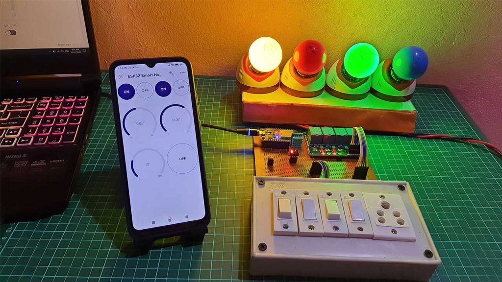
This is how you can implement the ESP32 EEPROM to remember last GPIO State. So this is a complete Internet & Manual Control Home Automation System Project with Real-Time Feedback using ESP32 & New Blynk 2.0 IoT App.

this looks pretty cool. Is there directions on how to set this up somewhere?