Battery Status Monitoring System using ESP8266 & Arduino IoT Cloud
Battery Monitoring System using ESP8266 & IoT
Overview: IoT Based Battery Monitoring System using ESP8266
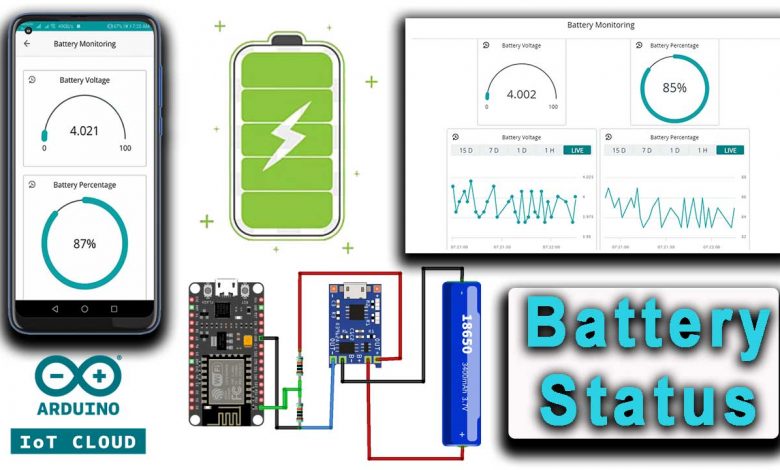
In this project, we will build a Battery Status Monitoring System using ESP8266 & Arduino IoT Cloud. Using this system we can monitor battery voltage and percentage from anywhere in the world. Therefore, this system is useful for monitoring battery charging /discharging status remotely.
As we know, the battery in any system or device is the main component because it powers the entire system. Hence, we need to monitor the voltage level of the battery. We all know that an improper system of charging and discharging may lead to battery damage or system failure. Most of the electrical/electronics devices have a Battery Management System (BMS). Actually, BMS monitors all the properties of the battery like the voltage, current, temperature & auto cut-off system. To ensure the proper safety and handling of Lithium-Ion or Lithium Polymer batteries.
The BMS can only monitor the condition of the battery and alarm the user through a battery indicator. But in this project, we have used the Internet of Things( IoT) technology which can directly notify the users remotely. now due to the use of the Internet of Things, we can directly notify the users remotely. The user can check the battery status on their smartphones or Computer Dashboard from anywhere in the world.
In this IoT-based Battery Monitoring System, we will use the NodeMCU ESP8266 board to send the battery status data to the Arduino IoT cloud. The IoT Cloud Dashboard will display the battery voltage along with the battery percentage in both the charging and discharging conditions.
Components Required
You will need the following components for the IoT Based Battery Monitoring System Project. You can purchase all the components online from the Amazon affiliate links provided below.
| S.N | Components Name | Quantity | |
|---|---|---|---|
| 1 | NodeMCU ESP8266 Development Board | 1 | https://amzn.to/3zRiok7 |
| 2 | TP4056 Charging Module | 1 | https://amzn.to/3yfP5Hp |
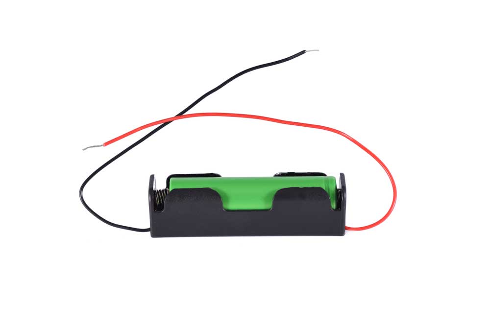
| 3 | 18650 Lithium Ion Battery | 1 | https://amzn.to/3iafIrL |
| 4 | Jumper cables | 6 | https://amzn.to/376GkDD |
| 5 | 100k resistor | 2 | https://amzn.to/3zML4dX |
Lithium-Ion Batteries
A lithium-ion battery or Li-ion battery is a rechargeable battery. These Lithium-ion batteries are widely and commonly used for portable electronics and electric vehicles.
In a Li-ion battery, the ions move from the negative electrode to the positive electrode while discharging, and vice versa when charging. It uses an intercalated lithium compound at the positive electrode and graphite at the negative electrode. This battery has a high energy density, no memory effect, and low self-discharge.
Nominal, Maximum & Cut-off Voltage
I have collected a few Lithium-Ion batteries that I have been using in most of my IoT-based Projects. Some batteries come with a BMS circuit for over-voltage protection. For smooth charging and short-circuit protection, etc.
Most of the Lithium-Ion batteries come with a nominal voltage of 3.7V. The maximum voltage is 4.2±0.5 when the battery is fully charged. You see the manufacturer datasheet, for your battery cut-off voltage because it varies depending on the type of battery that you are using. The battery that I am using in this project has a discharge cut-off voltage of 2.8V which is common. You can get batteries cut-off voltage of a lithium-ion battery between 2.5V-3V.
Also Read:
- IoT Based Pulse Oximeter Using ESP8266 & Blynk
- Interfacing PIR Sensor with ESP8266 and EasyIoT
- IoT Based Bidirectional Visitor Counter using ESP8266 & Blynk
- ESP32 based Patient Health Monitoring System
Circuit & Schematic Designing
We are going to design a simple system to monitor battery voltage and battery percentage along with charging and discharging status in Arduino IoT Cloud. A microcontroller is required to send those values to the IoT Platform. So, I choose a cheap and widely used NodeMCU ESP8266 board. It has a built-in WiFi chip that helps to connect to your wifi network and uploads data to the cloud server.
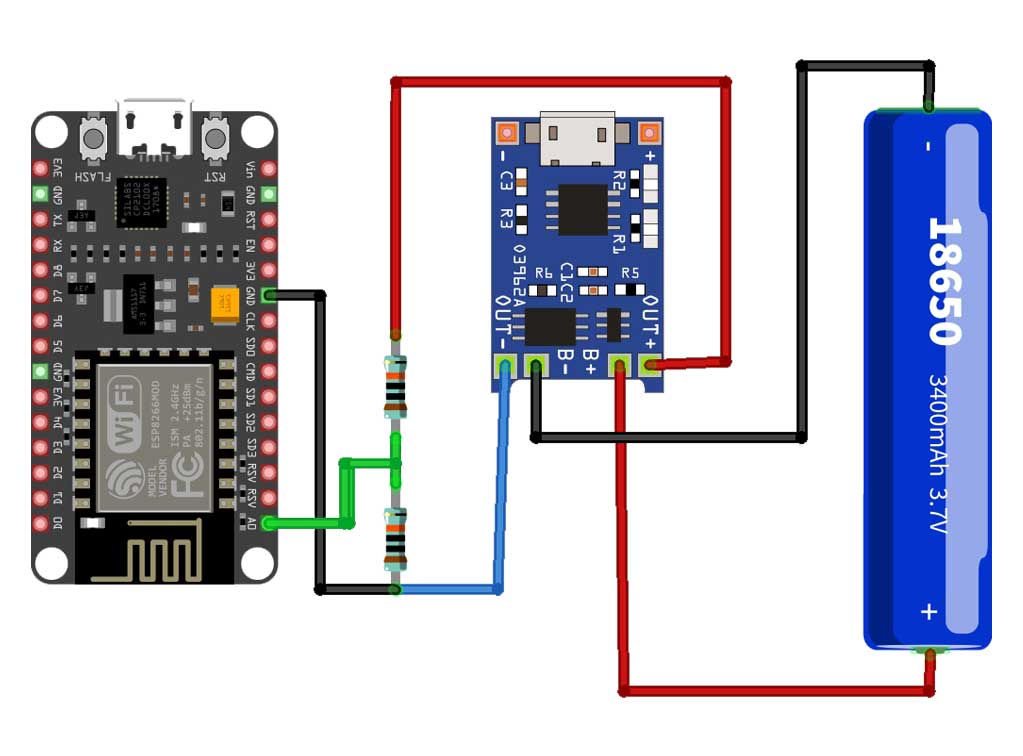
I am using the TP4056 module to charge the battery. This Module is best for Lithium-Ion batteries because it comes with the built-in battery management system. You can also use MCP73831 IC instead of TP4056.
The NodeMCU ESP8266 Chip can only support the input analog voltage of 3.3V. But Lithium-ion Battery voltage goes up to 4.2V. Hence, we need to form a voltage divider network and lower down the input analog voltage.
Voltage Divider Network Circuit
When the battery is fully charged, the maximum voltage is 4.2V and the discharge cut-off voltage is 2.8V. Once this is clear, any voltage lesser than 3.3V will be easily supported by ESP8266 Analog Pin.
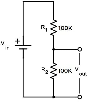
So, we will first step down to the upper voltage level. So, to do that I will use a Pair of 100K resistors. It will convert the source voltage from 4.2V to 2.1V. Similarly, the cut-off voltage is also stepped down from 2.8V to 1.4V. Now, both upper and lower voltage is supported by a NodeMCU ESP8266 Analog pin.
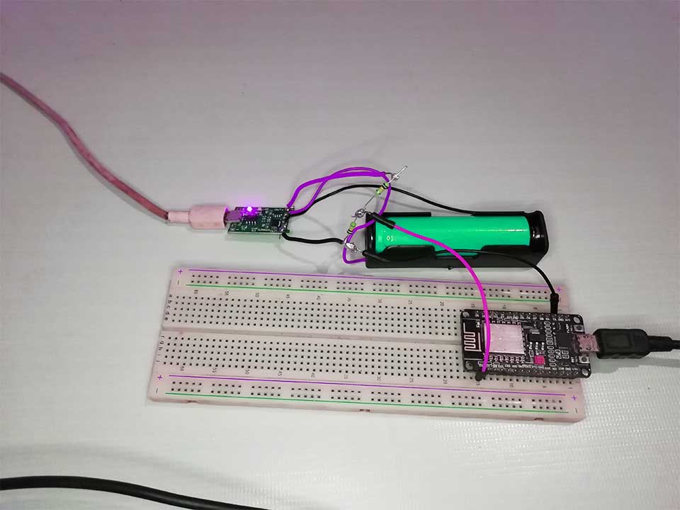
Here is a complete assembly of an IoT based Battery Monitoring project. The connection shown here is the same as shown in the above circuit diagram. For testing purposes, you can use a lithium-ion battery of any capacity. Here, for demonstration, I am using a 18650 Lithium-ion battery with a capacity of 2500mAh.
Project PCB Gerber File & PCB Ordering Online
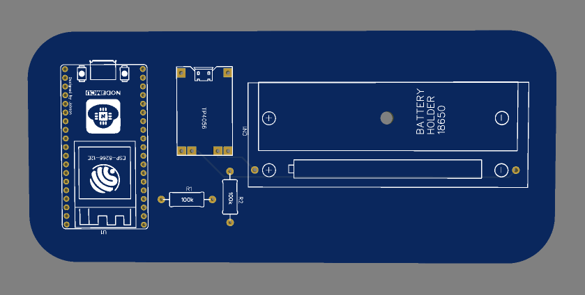
As I have assembled the circuit on breadboard but, you can order a custom PCB for this project. So, I designed the PCB Board for ESP8266 based Battery Monitoring System using EasyEDA. The PCB looks something like this.
I gave the Gerber File for the PCB below. You can simply download the Gerber File and order the PCB from https://www.PCBWay.com/
Now you can visit the PCBWay official website by clicking here: https://www.pcbway.com/. So it will direct you to the PCBWay website.
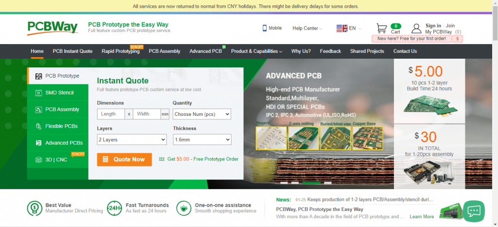
You can now upload the Gerber File to the Website and place an order. The PCB quality is superb & high. That is why most people trust PCBWay for PCB & PCBA Services.
Setting up Arduino IoT Cloud
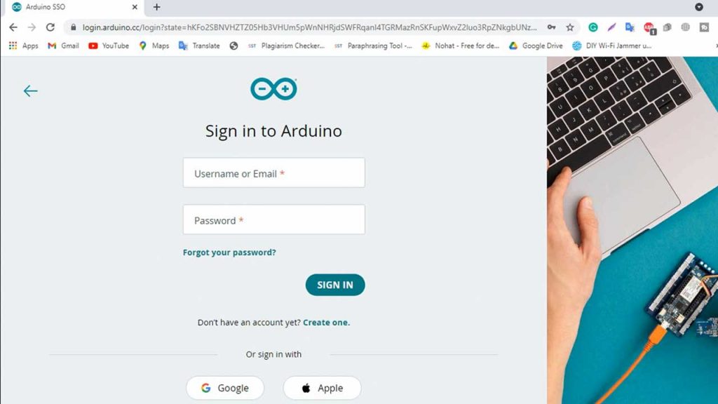
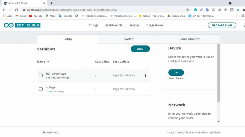
To Monitor the Battery Data on the Arduino IoT Cloud, you first need to set up the IoT Cloud Dashboard. To set up the Arduino IoT Cloud server, visit https://create.arduino.cc/. Create an account or simply sign in if you created the account earlier. Then create a new Thing with the following details.
Then on the things tab create two global variables bat_percentage and voltage of integer and floating-point number type respectively.
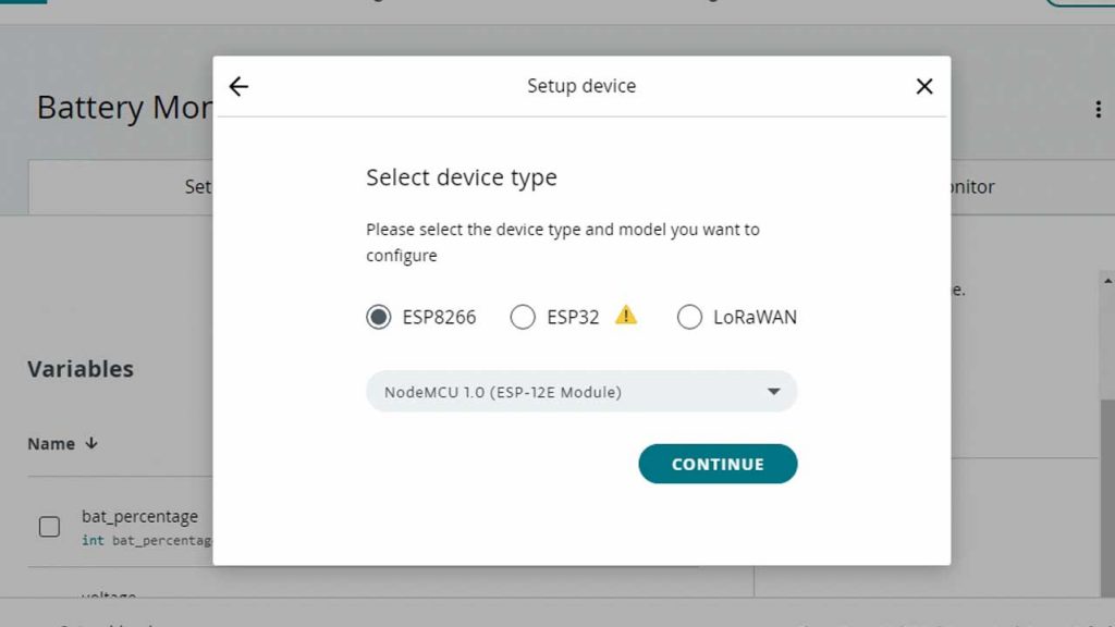
Now, you need to add a device. To do that Click on add device and click on add third party device. Choose ESP8266 and select NodeMCU 1.0 ( ESP8266 12E) board. Click on continue and provide your device name. For Demonstration, I am providing “My_ESP8266 ”.
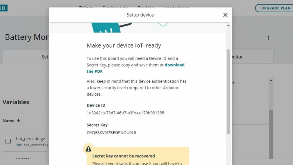
Finally, Click on Download the PDF and save it securely. It contains a Device ID and Secret key you will need later in the programming.
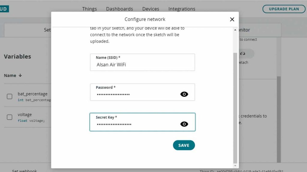
Now Click on Add network and provide the WiFi SSID, Password, and Device Secret key. Then click on save to link your wifi network.
We need to build a dashboard to visualize the data. So, let’s move to the Dashboard Tab and create a new dashboard called “Battery Monitoring”. Now click on Add to add widgets to your dashboard. In this tutorial, we will use one gauge, one percentage, and two chart widgets to visualize our data.
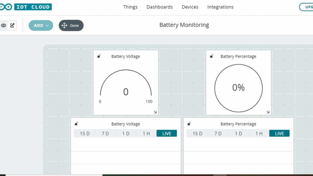
The First Gauge is for monitoring battery voltage. So we will configure it as “Battery Voltage” and link a voltage variable from things that we have created earlier. Similarly, for “Battery Percentage”, we will link a bat_percentage variable from things. In a final step, we will configure one chart widget for Battery Voltage and the other for Battery Percentage. Finally, we have created our dashboard. Now let’s program our NodeMCU ESP8266 to send data to the IoT Cloud.
Source Code/Program
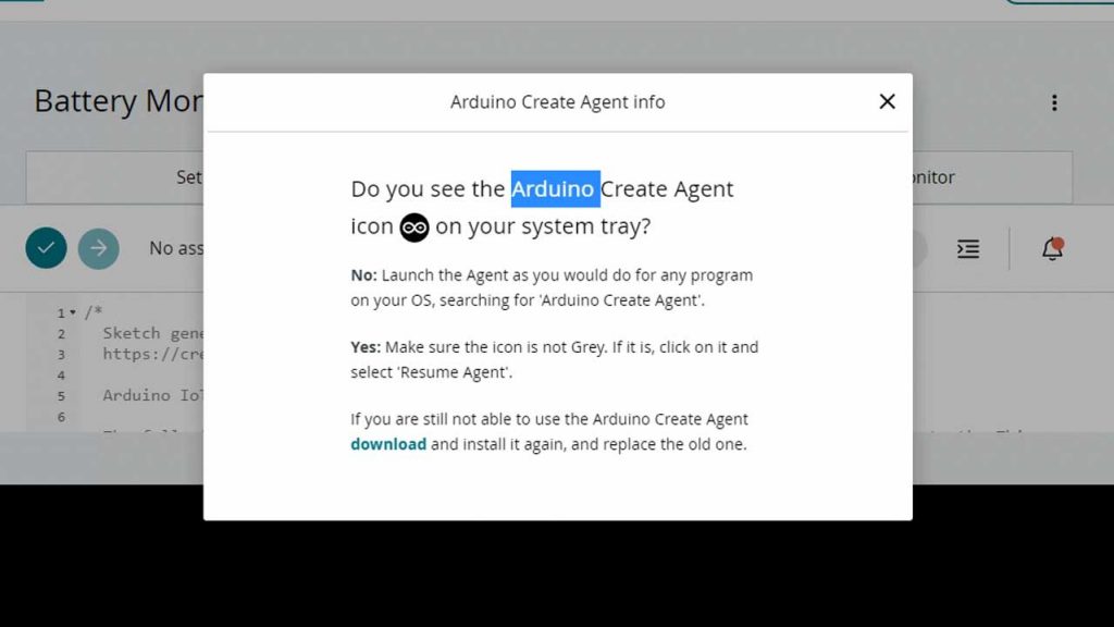
Now the best part of using Arduino IoT Cloud is, you can program your microcontroller board from the browser. You don’t separate software like Arduino IDE. Simply install and run “Arduino Create Agent”. You can also get instructions from the same web interface.
Go back to the Things Tab then click on the sketch. Simply, copy and paste the code provided below. Now, simply compile and upload the code to your NodeMCU board.
/*
  Sketch generated by the Arduino IoT Cloud Thing "Battery Monitoring"
  https://create.arduino.cc/cloud/things/b7067d44-2084-45ca-bb06-424a1af2eb74

  Arduino IoT Cloud Variables description

  The following variables are automatically generated and updated when changes are made to the Thing

  float voltage;
  int bat_percentage;

  Variables which are marked as READ/WRITE in the Cloud Thing will also have functions
  which are called when their values are changed from the Dashboard.
  These functions are generated with the Thing and added at the end of this sketch.
*/

#include "thingProperties.h"
int analogInPin  = A0;    // Analog input pin
int sensorValue;
float calibration = 0.36; // Check Battery voltage using multimeter & add/subtract the value

void setup() {
  // Initialize serial and wait for port to open:
  Serial.begin(9600);
  // This delay gives the chance to wait for a Serial Monitor without blocking if none is found
  delay(1500);

  // Defined in thingProperties.h
  initProperties();

  // Connect to Arduino IoT Cloud
  ArduinoCloud.begin(ArduinoIoTPreferredConnection);

  /*
     The following function allows you to obtain more information
     related to the state of network and IoT Cloud connection and errors
     the higher number the more granular information you’ll get.
     The default is 0 (only errors).
     Maximum is 4
 */
  setDebugMessageLevel(2);
  ArduinoCloud.printDebugInfo();
}

void loop() {
  ArduinoCloud.update();
 sensorValue = analogRead(analogInPin);
  voltage = (((sensorValue * 3.3) / 1024) * 2 + calibration); //multiply by two as voltage divider network is 100K & 100K Resistor

  bat_percentage = mapfloat(voltage, 2.8, 4.2, 0, 100); //2.8V as Battery Cut off Voltage & 4.2V as Maximum Voltage

  if (bat_percentage >= 100)
  {
    bat_percentage = 100;
  }
  if (bat_percentage <= 0)
  {
    bat_percentage = 1;
  }

  Serial.print("Analog Value = ");
  Serial.print(sensorValue);
  Serial.print("t Output Voltage = ");
  Serial.print(voltage);
  Serial.print("t Battery Percentage = ");
  Serial.println(bat_percentage);
  delay(1000);

}

float mapfloat(float x, float in_min, float in_max, float out_min, float out_max)
{
  return (x - in_min) * (out_max - out_min) / (in_max - in_min) + out_min;
}
Demonstration: Battery Monitoring System using ESP8266 on Arduino IoT Cloud
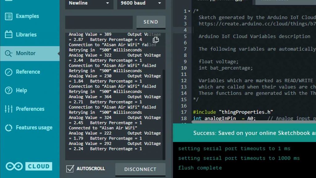
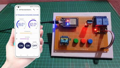
After successful upload of the program, open the Serial Monitor at the baud rate of 9600. The NodeMCU ESP8266 will try connecting to the WiFi Network. Once it connects successfully to your WiFi Network, it will display the Analog voltage Value along with Battery Voltage & Percentage.
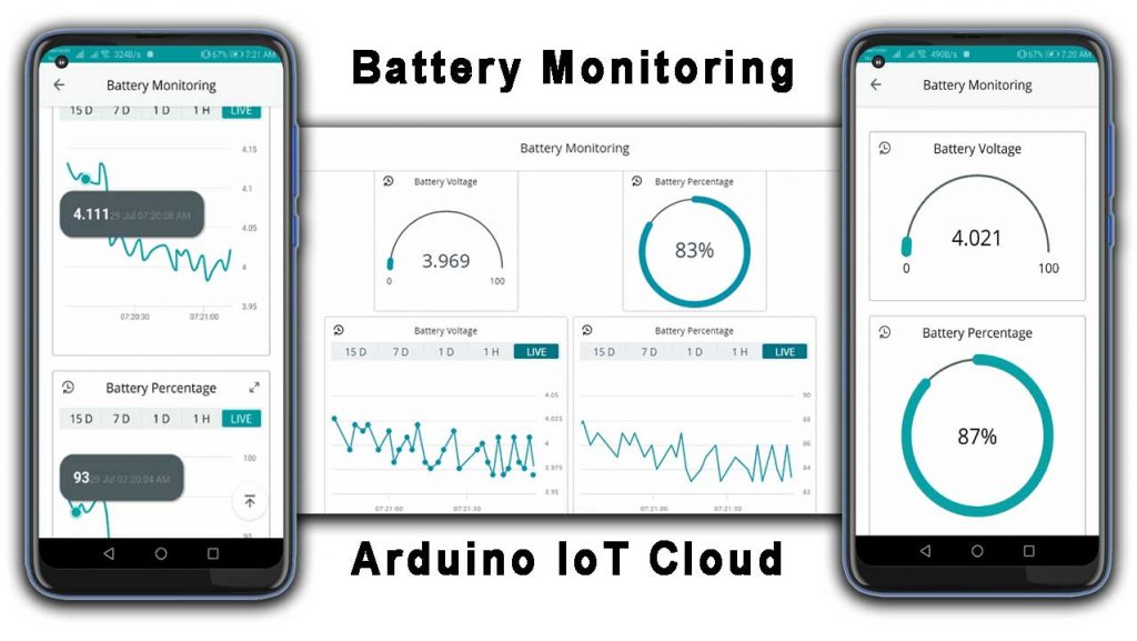
Similarly, on the dashboard, you can monitor the same values in very beautiful widgets. In a chat, you can see the graph rising up when charging and going down when discharging.
Fixing Voltage Value by Calibration
As we have used a pair of 100k resistors to fix the voltage input problem of the Analog pin of NodeMCU. But, these resistors have some tolerance of about ±5%. Because of this, the resistor value is between 95K to 105K. Hence, it directly affects both output voltage and analog signal output.
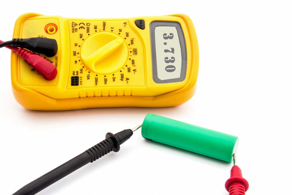
To overcome this issue, we can compare the voltage difference between the Serial Monitor reading and the Multimeter reading. You need to simply read the output voltage at the TP4056 output terminal. You can use a multimeter to measure it. If you don’t have a multimeter, you can make your own using Arduino UNO.
Subtract the Multimeter voltage readings from the value obtained from Serial Monitor.
You can add that value in this line of code as a calibration factor.
float calibration = 0.36; // Check Battery voltage using multimeter & add/subtract the value
Finally, the voltage error is fixed. Now, you can enjoy, we have successfully designed an IoT Based Battery Status Monitoring System using ESP8266 and get the reading on Arduino IoT Cloud.
Video Tutorial & Guide: IoT Based Battery Monitoring System
Conclusion
So, this is how we made an IoT Based Battery Status Monitoring System using ESP8266 and Arduino cloud. I hope this project will help you a lot in monitoring your battery status for IoT Projects. If you think this project is helpful, please kindly share it with your friends. It will make my day. Keep learning… & supporting…


Please help.
When compiling the program: “Battery Status Monitoring System using ESP8266 & Arduino IoT Cloud” it wrote this problem. Where is the mistake.
/home/builder/.arduino15/packages/esp8266/tools/xtensa-lx106-elf-gcc/2.5.0-3-20ed2b9/bin/../lib/gcc/xtensa-lx106-elf/4.8.2/../../../../xtensa-lx106-elf/bin/ld: /tmp/arduino-build-E94A4442044C4C6F85D4DB801E1CB970/sketch/objs.a(MonBAT.ino.cpp.o):(.text._Z14initPropertiesv+0x24): undefined reference to `onBatPercentageChange()’
/home/builder/.arduino15/packages/esp8266/tools/xtensa-lx106-elf-gcc/2.5.0-3-20ed2b9/bin/../lib/gcc/xtensa-lx106-elf/4.8.2/../../../../xtensa-lx106-elf/bin/ld: /tmp/arduino-build-E94A4442044C4C6F85D4DB801E1CB970/sketch/objs.a(MonBAT.ino.cpp.o):(.text._Z14initPropertiesv+0x34): undefined reference to `onVoltageChange()’
collect2: error: ld returned 1 exit status
Error during build: exit status 1
I’m experiencing the same issue rn.
Has anyone got this sketch to compile?
Check this ;
/*
Sketch generated by the Arduino IoT Cloud Thing “Untitled”
https://create.arduino.cc/cloud/things/d4e617d2-366d-4f3d-8a72-2b2c1d764024
Arduino IoT Cloud Variables description
The following variables are automatically generated and updated when changes are made to the Thing
float voltage;
int bat_percentage;
Variables which are marked as READ/WRITE in the Cloud Thing will also have functions
which are called when their values are changed from the Dashboard.
These functions are generated with the Thing and added at the end of this sketch.
*/
#include “thingProperties.h”
int analogInPin = A0; // Analog input pin
int sensorValue;
float calibration = 0.36; //
void setup() {
// Initialize serial and wait for port to open:
Serial.begin(9600);
// This delay gives the chance to wait for a Serial Monitor without blocking if none is found
delay(1500);
// Defined in thingProperties.h
initProperties();
// Connect to Arduino IoT Cloud
ArduinoCloud.begin(ArduinoIoTPreferredConnection);
/*
The following function allows you to obtain more information
related to the state of network and IoT Cloud connection and errors
the higher number the more granular information you’ll get.
The default is 0 (only errors).
Maximum is 4
*/
setDebugMessageLevel(2);
ArduinoCloud.printDebugInfo();
}
void loop() {
ArduinoCloud.update();
// Your code here
sensorValue = analogRead(analogInPin);
voltage = (((sensorValue * 3.3) / 1024) * 2 + calibration); //multiply by two as voltage divider network is 100K & 100K Resistor
}
/*
Since BatPercentage is READ_WRITE variable, onBatPercentageChange() is
executed every time a new value is received from IoT Cloud.
*/
void onBatPercentageChange() {
// Add your code here to act upon BatPercentage change
}
/*
Since Voltage is READ_WRITE variable, onVoltageChange() is
executed every time a new value is received from IoT Cloud.
*/
void onVoltageChange() {
bat_percentage = mapfloat(voltage, 2.8, 4.2, 0, 100); //2.8V as Battery Cut off Voltage & 4.2V as Maximum Voltage
if (bat_percentage >= 100)
{
bat_percentage = 100;
}
if (bat_percentage <= 0)
{
bat_percentage = 1;
// Add your code here to act upon Voltage change
}
Serial.print("Analog Value = ");
Serial.print(sensorValue);
Serial.print("\t Output Voltage = ");
Serial.print(voltage);
Serial.print("\t Battery Percentage = ");
Serial.println(bat_percentage);
delay(1000);
}
float mapfloat(float x, float in_min, float in_max, float out_min, float out_max)
{
return (x – in_min) * (out_max – out_min) / (in_max – in_min) + out_min;
}
Hi
I did your setup, but i only used the ESP board with 1 batt 18650@3.2v. no TP4056 Charging Module
But on the dashboard the batt voltage and the percentage are the same value (21) how to show the voltage on the batt gauge and the percentage separate.
here is my code
#include “thingProperties.h”
int analogInPin = A0; // Analog input pin
int sensorValue;
float calibration = -3.5; // Check Battery voltage using multimeter & add/subtract the value
void setup() {
// Initialize serial and wait for port to open:
Serial.begin(9600);
// This delay gives the chance to wait for a Serial Monitor without blocking if none is found
delay(1500);
// Defined in thingProperties.h
initProperties();
// Connect to Arduino IoT Cloud
ArduinoCloud.begin(ArduinoIoTPreferredConnection);
/*
The following function allows you to obtain more information
related to the state of network and IoT Cloud connection and errors
the higher number the more granular information you’ll get.
The default is 0 (only errors).
Maximum is 4
*/
setDebugMessageLevel(2);
ArduinoCloud.printDebugInfo();
}
void loop() {
ArduinoCloud.update();
sensorValue = analogRead(analogInPin);
voltage = (((sensorValue * 3.3) / 1024) * 2 + calibration); //multiply by two as voltage divider network is 100K & 100K Resistor
bat_percentage = mapfloat(voltage, 2.8, 4.2, 0, 100); //2.8V as Battery Cut off Voltage & 4.2V as Maximum Voltage
if (bat_percentage >= 100)
{
bat_percentage = 100;
}
if (bat_percentage
{
bat_percentage = 1;
}
Serial.print(“Analog Value = “);
Serial.print(sensorValue);
Serial.print(“\t Output Voltage = “);
Serial.print(voltage);
Serial.print(“\t Battery Percentage = “);
Serial.println(bat_percentage);
delay(1000);
}
float mapfloat(float x, float in_min, float in_max, float out_min, float out_max)
{
return (x – in_min) * (out_max – out_min) / (in_max – in_min) + out_min;
}
here is my code. running properly. u can use it
#include “thingProperties.h”
int analogInPin = A0; // Analog input pin
int sensorValue;
float calibration = 0.2; // Check Battery voltage using multimeter & add/subtract the value
void setup() {
// Initialize serial and wait for port to open:
Serial.begin(9600);
// This delay gives the chance to wait for a Serial Monitor without blocking if none is found
delay(1500);
// Defined in thingProperties.h
initProperties();
// Connect to Arduino IoT Cloud
ArduinoCloud.begin(ArduinoIoTPreferredConnection);
/*
The following function allows you to obtain more information
related to the state of network and IoT Cloud connection and errors
the higher number the more granular information you’ll get.
The default is 0 (only errors).
Maximum is 4
*/
setDebugMessageLevel(2);
ArduinoCloud.printDebugInfo();
}
void loop() {
ArduinoCloud.update();
onVoltageChange();
onBatPercentageChange();
Serial.print(“Analog Value = “);
Serial.print(sensorValue);
Serial.print(“\t Output Voltage = “);
Serial.print(voltage);
Serial.print(“\t Battery Percentage = “);
Serial.println(bat_percentage);
delay(1000);
}
void onBatPercentageChange() {
bat_percentage = mapfloat(voltage, 2.8, 4.2, 0, 100); //2.8V as Battery Cut off Voltage & 4.2V as Maximum Voltage
if (bat_percentage >= 100)
{
bat_percentage = 100;
}
if (bat_percentage <= 0)
{
bat_percentage = 1;
}
}
void onVoltageChange() {
sensorValue = analogRead(analogInPin);
voltage = (((sensorValue * 5.0) / 1023) / (1/3.0) + calibration); //multiply by two as voltage divider network is 100K & 100K Resisto
}
float mapfloat(float x, float in_min, float in_max, float out_min, float out_max)
{
return (x – in_min) * (out_max – out_min) / (in_max – in_min) + out_min;
}