Relay Control with Arduino & DWIN Display
Arduino & DWIN HMI Display for Relay Control
In this project, we will create an 8-channel relay control system using Arduino and a DWIN Display. The system allows you to control your home appliances using the DWIN Display and Arduino, along with relays. You can increase the number of devices that can be controlled up to 16 by adding additional relays, but for this demonstration, we will use 8-channel relays to control eight different appliances.
- Overview: Relay control with DWIN display and Arduino
- Components Required
- Install the Required Software and tools
- GUI Designing
- Preparing the DWIN display for uploading firmware.
- Format SD Card & Upload Firmware
- Circuit Diagram
- About the Sponsor PCBWay
- Arduino Code
- Arduino Code Explanation
- Uploading Program Code
- Demonstration: Arduino and DWIN Display for Relay Control
- Conclusion
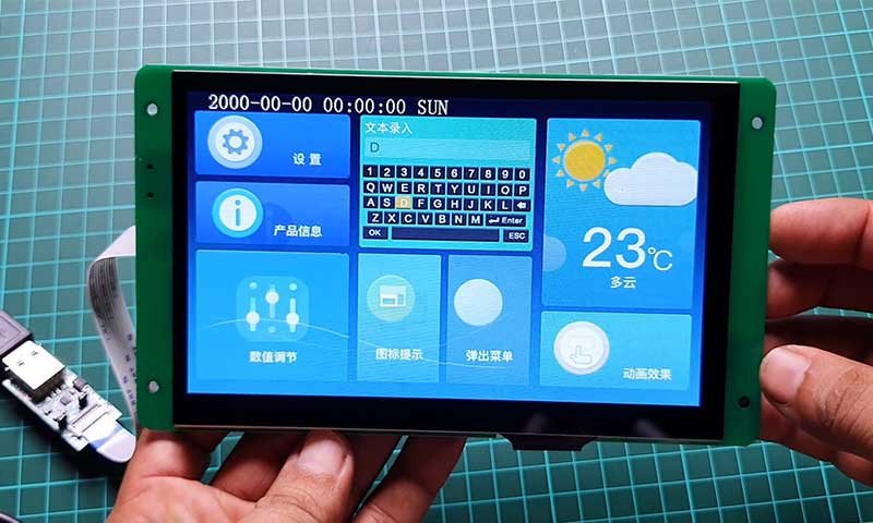
If you are unfamiliar with the DWIN HMI Display, there is a comprehensive getting started tutorial available for the (DMG80480C070_04WTC) Display. We have previously used the DWIN Touch Display to build weather monitoring systems, home automation systems, and thermostat control systems.
Overview: Relay control with DWIN display and Arduino
There are many potential applications for a relay control system using an Arduino and DWIN Display, including controlling electrical devices, automating processes, and integrating with other systems or devices. The system can be customized and expanded as needed by adding additional relays, sensors, or other components.
I am using a 7-inch DWIN HMI (DMG80480C070_04WTC) Display to monitor and control AC Home Appliances. Today’s tutorial will be a bit longer because to create a relay control system using an Arduino and DWIN Display, We first download and install the required software and tools. Design the Display UI for controlling relays. Upload firmware to the display. Then set up and connect the hardware according to the appropriate wiring diagram. The Arduino must then be programmed using the Arduino IDE for controlling the relays with DWIN Display. Once the code has been written and uploaded to the Arduino, the relay control system should be functional and able to control the devices or systems connected to the relays.
Components Required
The following components are needed to build an 8-channel relay control system using Arduino and DWIN HMI Display. You can find links to purchase these components below:
| S.N | Components Name | Quantity | Purchase Links |
|---|---|---|---|
| 1 | Arduino Nano board | 1 | https://amzn.to/3OnuHeB |
| 2 | 7-inch DWIN HMI Display | 1 | https://aliexpress.com/Dwin-Display |
| 3 | 8-Channel Relay Module | 1 | https://amzn.to/3HKpdLr |
| 4 | Jumper Wires | 20 | https://amzn.to/2JWSR44 |
| 5 | Breadboard | 1 | https://amzn.to/3n33uRT |
Install the Required Software and tools
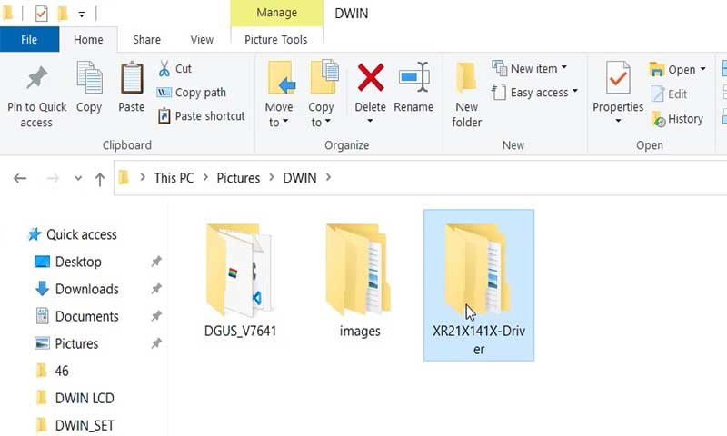
To use a DWIN display with an Arduino, you will need to visit the DWIN Global website and download the DGUS software and XR21X driver from the “Tools” section of the “Downloads” page. Extract both of these files after downloading them. You do not need to install the DGUS software, but you will need to install the XR21X driver on your PC. Once the driver is installed, you will be able to establish communication between the HDL662B board and your PC. The DGUS software includes tools like the ICL tool, font generating tool, and image resizing tool.
GUI Designing
After installing the DGUS Software and driver. Open the DGUS.exe file. By default, the software language is set to Chinese. To change it to English, go to the settings menu and select English as the preferred language.
Save the changes and the software will now display in English.
Note: These instructions may vary depending on the version of the DGUS software you are using. If you have any difficulties or questions, you should refer to the user manual or contact the manufacturer for further assistance.
Creating New project
To create a new project in the DGUS software, follow these steps:
- Click on the “New” button to start a new project.
- Select a screen resolution of 800×480 pixels.
- Choose the folder path where you want to save your project. In this example, you can create a new folder called “Relay Control” and select that as the project folder.
- Prepare the necessary images or icons for your project. In this example, I have already created these images and icons.
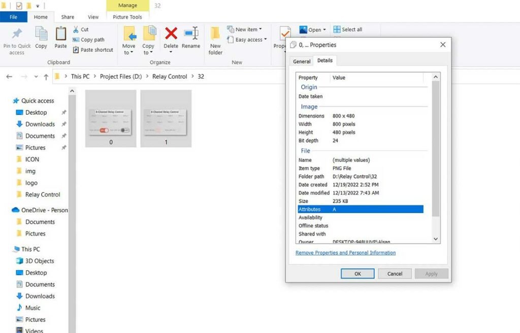
You should name your images and icon folder using numbers such as 32, 34, 36, 42, 46, 56, 58, 62, 64, etc. because the memory on the DGUS device is divided into different sections and you will need to create an ICL file for these pictures later. This will help you keep track of the images and icons for your project and ensure that they are properly organized in the ICL file. It is recommended to follow this naming convention to make it easier to organize and manage your project.
Making Project Images and icons ready
In this tutorial Under 32 folder, I have placed two images of 800×480 pixels for my UI. Similarly, in the 34 folder, I have placed icon files.
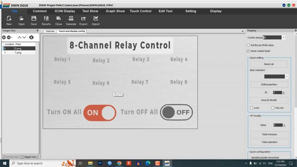
Now, go back to DGUS and add those two images from the 32 folder.
Generate ICL File
To create ICL files for your images in the DGUS software, follow these steps:
- Go to the settings menu and click on DGUS.
- A new window will pop up. Click on the ICL Tool.
- In the ICL Tool, select the images that you want to include in the ICL file.
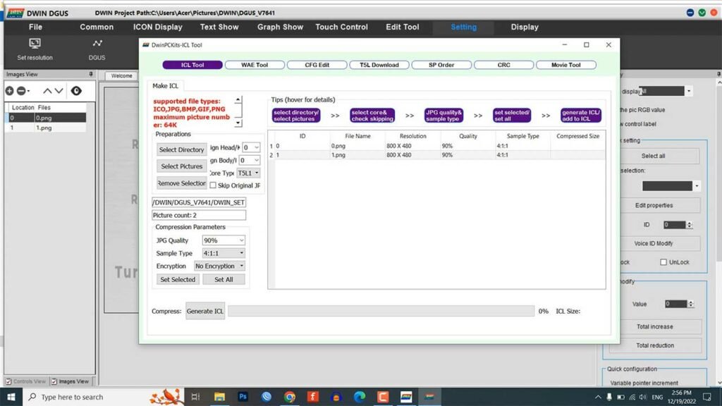
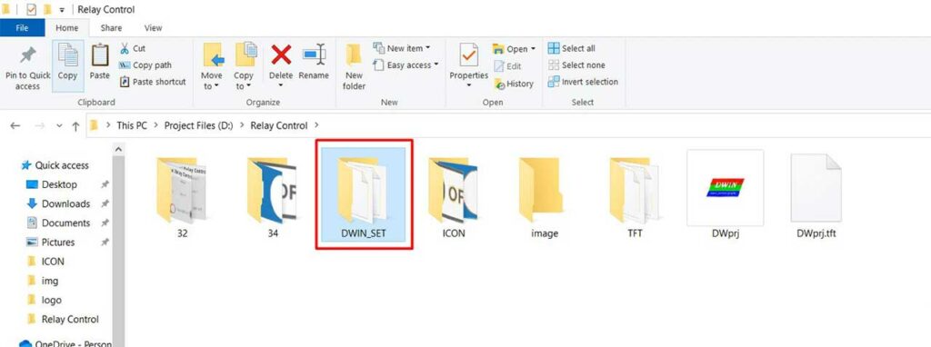
- Generate an ICL file for the selected images and save it with the name “32” in the DWIN_SET folder.
- Similarly, select the button’s icons and generate an ICL file as “34” in the same DWIN_SET folder.
- Repeat this process for any additional images or icons that you want to include in your project.
Once you have generated the necessary ICL files, you can then proceed to add functions to your user interface (UI).
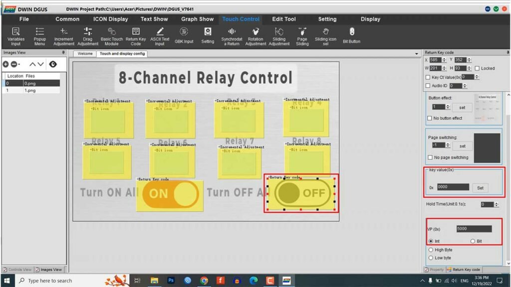
Configure Toggle Switch Design
To create a control toggle switch for a relay using the DGUS software, follow these steps:
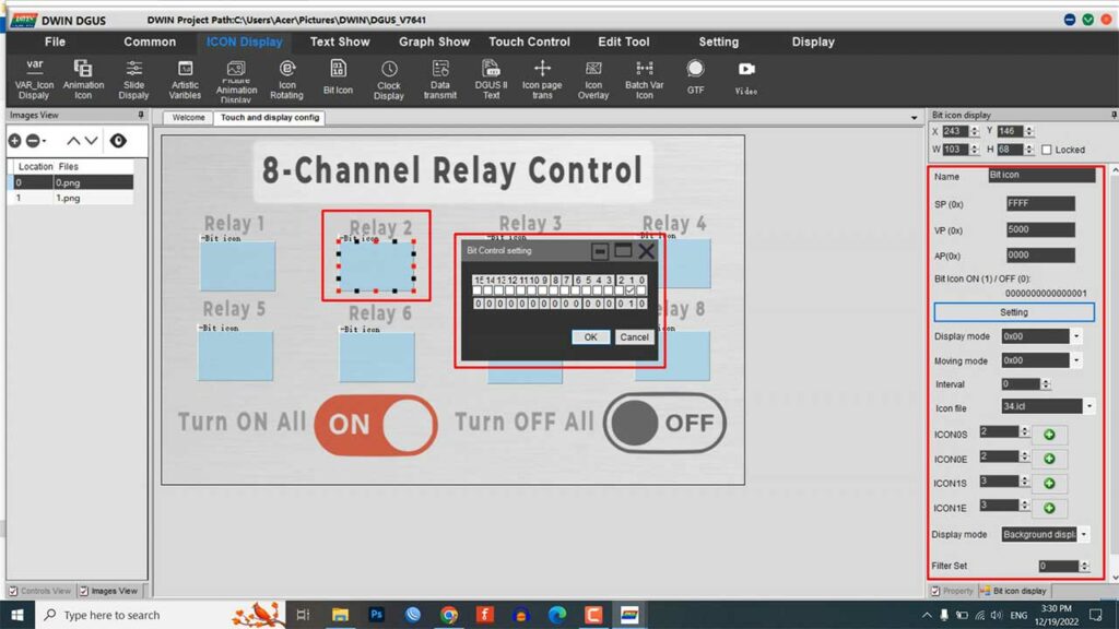
- From the icon display menu, select the Bit Icon tool.
- Click on the area where you want to display your icon and resize the module as needed.
- In the Bit Icon settings, set the SP address to FFFF, the VP address to 5000, and the AP address to 0000.
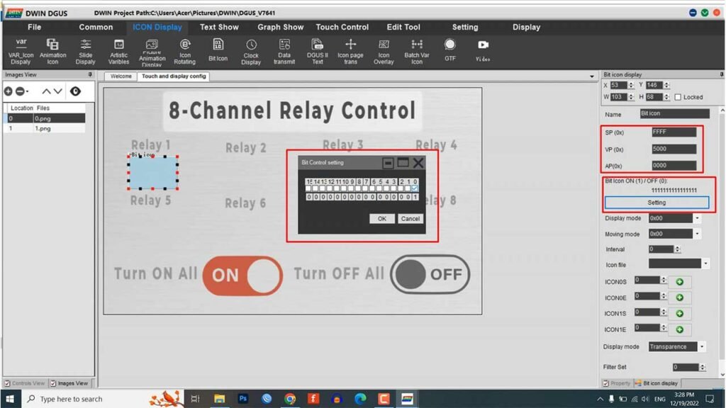
- Set the bit control settings for the desired number of relays. For example, if you want to control 8 relays, you can set the bit control settings to 0 for relay 1, 1 for relay 2, 2 for relay 3, and so on up to 7 for relay 8.
- Select your icon file (e.g. 34.icl) and choose the OFF and ON icons for the two states.
- Leave the other settings as they are.
- Copy the Bit icon by pressing Ctrl+C.
- Paste the copied Bit icon with Ctrl+V and drag the module to the desired location.
- Repeat this process until you have created a Bit icon for each relay that you want to control.
- Set the bit control settings for each module in incremental order. For example, if you are controlling 8 relays, the first module should have a bit control setting of 0, the second module should have a setting of 1, and so on up to 7 for the eighth module.
Configure Touch Control
To create an incremental adjustment module for controlling a relay using the DGUS software, follow these steps:
- From the touch control menu, select the Increment Adjustment module.
- Resize the module as desired.
- Enable data auto uploading and set the VP address to 5000.
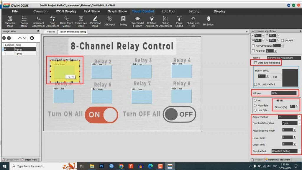
- In the “Bit” parameter, enter the number that matches the bit control setting that you set in the Bit Icon element. For example, if the Bit Icon element has a bit control setting of 0, you should enter 0 in the “Bit” parameter of the Increment Adjustment module.
- Set the Adjust method to ++ and the Over the Limit Operation to Cycle.
- Set the Step Length to 1 and the Upper Limit to 1.
- Set the Touch Effect to Constant Setting.
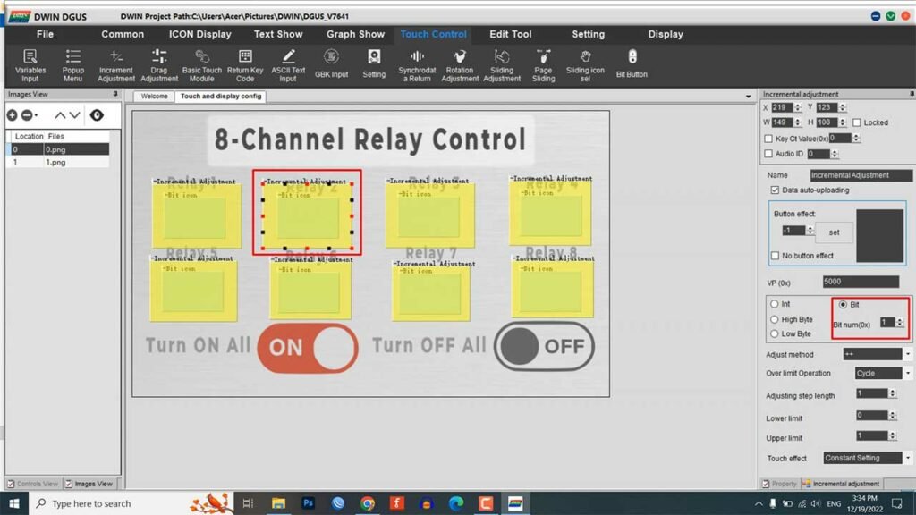
- Copy and paste the Increment Adjustment module and set the “Bit” parameter accordingly for each relay that you want to control. You can adjust the element size as needed.
Touch Control with Return Key Code
To create ON and OFF buttons for controlling multiple relays using the DGUS software, follow these steps:
- From the touch control menu, select the Return Key Code tool.
- Enable data auto uploading and set the Button Effect to 1.png.
- Set the main parameter to Zeroing and Filling All Bits. This will allow you to turn off or turn on all the relays at once.
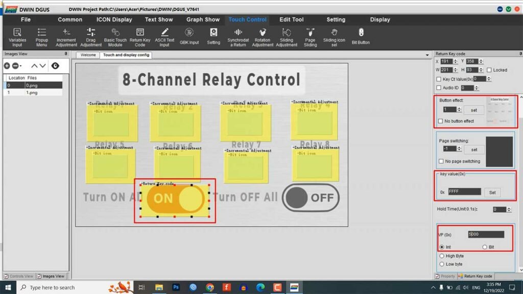
- Set the Key Value to FFFF and the VP address to 5000.
- Copy the Return Key Code module and paste it on the OFF button. Change the Key Value to 0000 to turn off all the relays.
- Repeat this process for any additional relays that you want to control.
Once you have added all the necessary modules to your UI, click on “Save and Generate” to generate 13 touch files, 14 show files, and 22 config bin files.
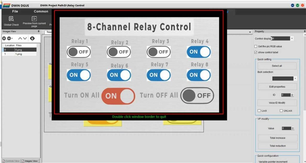
Preview of Newly Created GUI
Now you can preview the UI of our project from the display menu. Click on preview from the first page and you can see our newly created UI in a pop-up window.
Now let’s prepare our DWIN Display and SD Card for uploading the project to our Display.
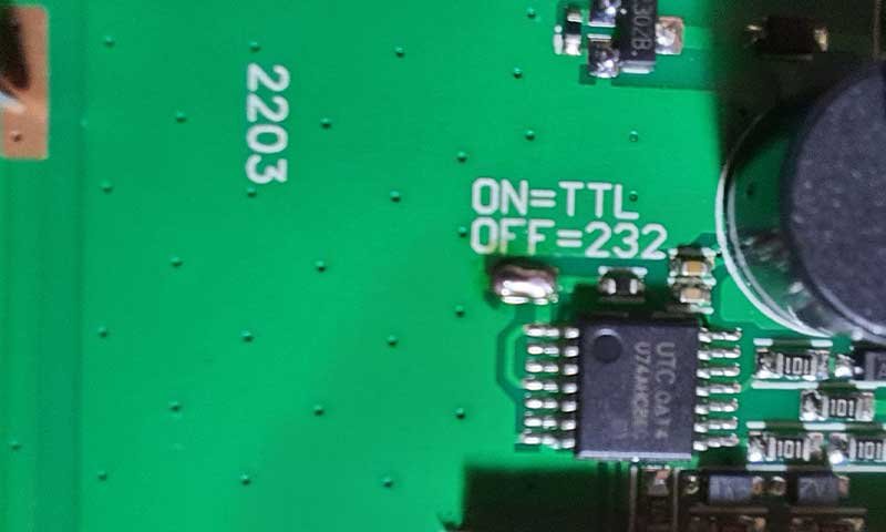
Preparing the DWIN display for uploading firmware.
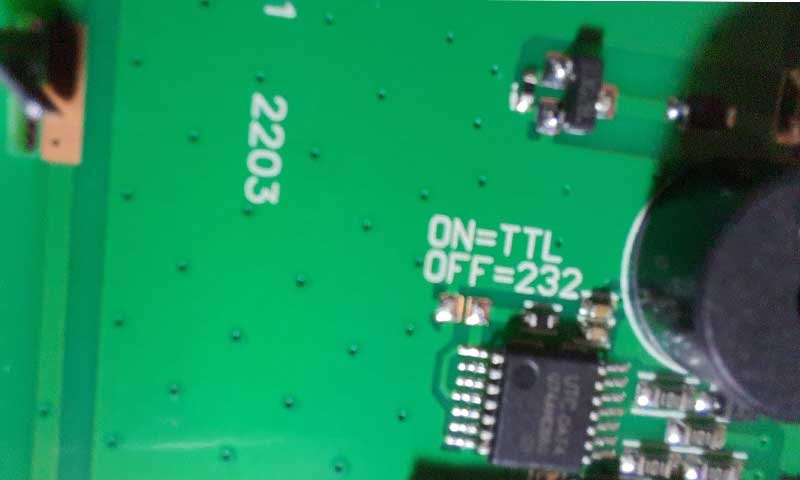
To use a display with an Arduino, you need to pay attention to a small jumper on the display. This jumper determines how the serial port will operate. If you connect the jumper, the serial port will operate in TTL/UART mode. When you do not connect the jumper, the serial port will operate in RS232 mode. If your display does not come with the jumper installed, you will need to either connect the two points or solder a 0 Ohm resistor to the jumper in order to properly configure the serial port. Next, you need to prepare a memory card and flash the display.
Format SD Card & Upload Firmware
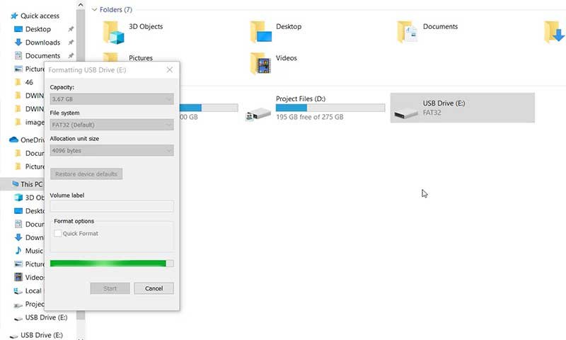
To use a Micro SD card with this system, it must be 16GB or smaller and formatted in the FAT32 file system. Follow these instructions to format the card:
- Insert the SD card into a card reader or SD card slot on your computer.
- Open “My Computer” or “This PC” and find the SD card listed under “Devices and drives.”
- Right-click on the SD card and select “Format.”
- In the “Format” window, choose “FAT32” from the “File system” dropdown menu.
- Ensure that the “Quick Format” box is unchecked.
- Click “Start” to begin formatting the SD card.
- Wait for the formatting process to complete, which may take a few minutes depending on the size of the SD card.
- Click “Close” when the process is finished.
To flash the Firmware file on DWIN Display:
- Copy the DWIN_SET folder onto your SD card.
- Insert the SD card into the LCD display.
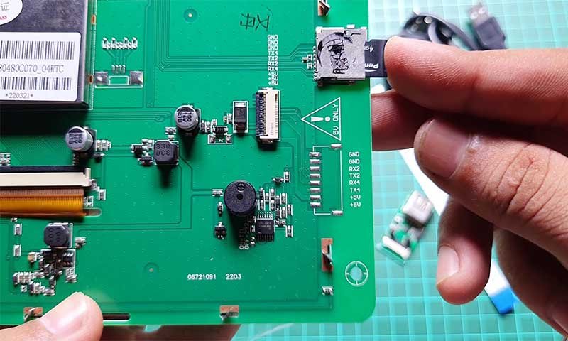
- Connect the USB cable to the HDL board.
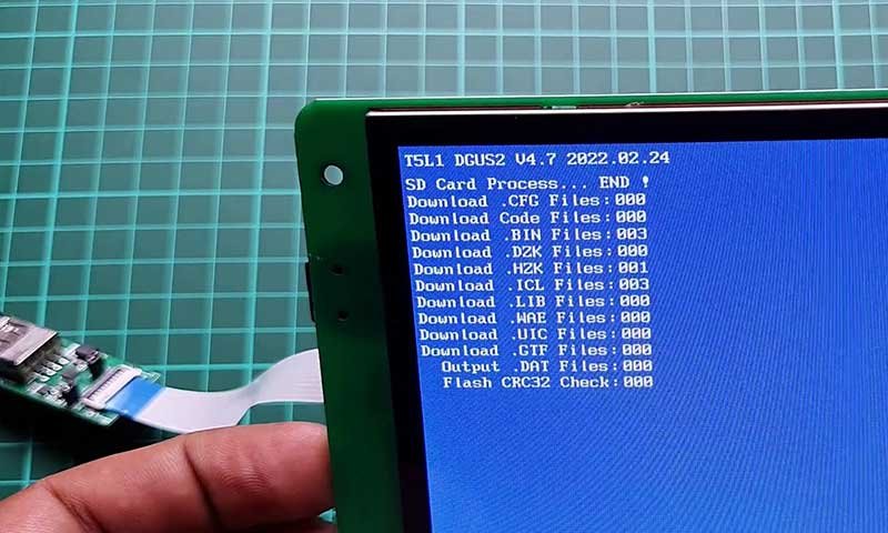
- Power the LCD and wait for the download process to complete.
- Remove the USB from the PC and the SD card from the display.
- Reconnect the USB cable.
The newly flashed UI should now be displayed on the LCD. After uploading the project file to the display, this is the result of our newly created UI.
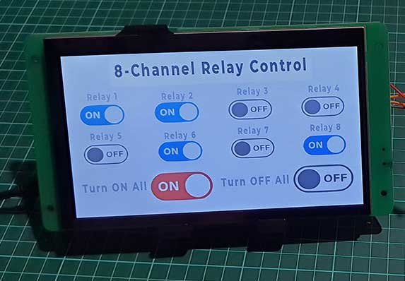
Circuit Diagram
After completing the design of the GUI for the display, you will need to connect the 8-channel relay module to the Arduino board. You can use any 5V compatible Arduino board for this purpose, such as an Arduino Nano. To establish serial communication between the display and the Arduino, you will need to connect the relay module to the D2 to D9 pins of the Arduino and the RX2 and TX2 pins of the DWIN HMI display to the RX2 and TX2 pins of the Arduino, respectively. Refer to the circuit diagram for the correct connections.
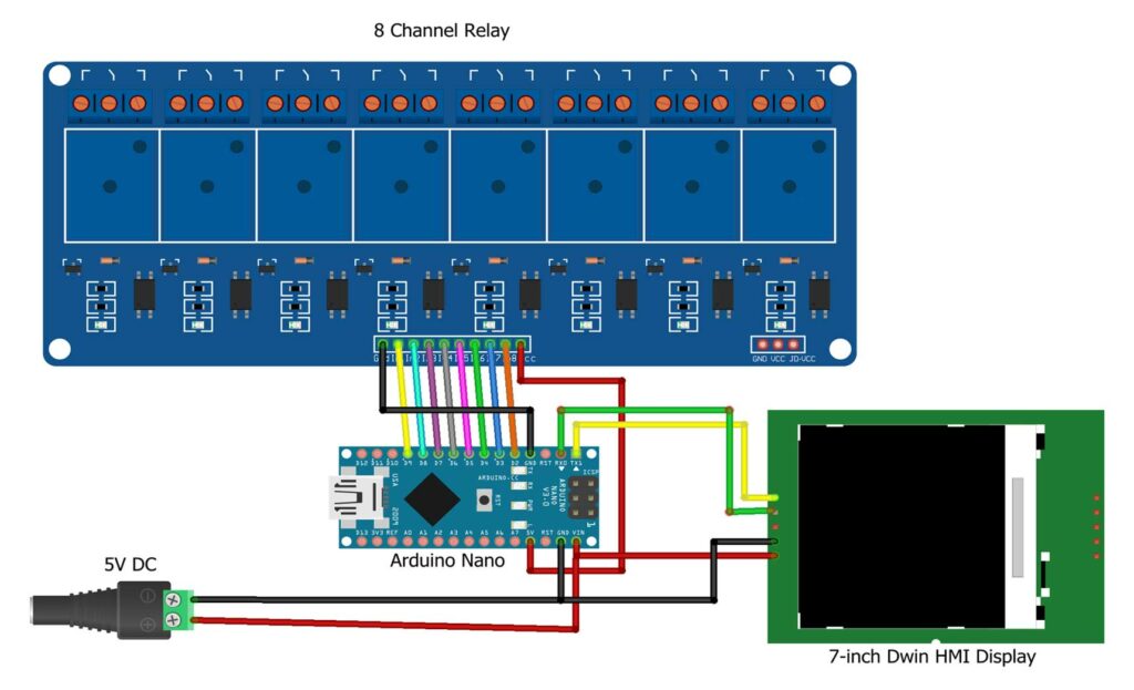
Note: If you are using separate power sources for the Arduino and the LCD, make sure to connect the GND (ground) pin of the display to the GND pin of the Arduino. This will ensure that both devices are using the same reference voltage.
About the Sponsor PCBWay
PCBWay.com played a pivotal role in the successful completion of this project. Their exceptional support and assistance were invaluable throughout the entire PCB design and manufacturing process. If you’re looking to embark on your own PCB project, I highly recommend checking out their website. PCBWay offers an impressive range of high-quality, reliable PCBs starting at just $5.
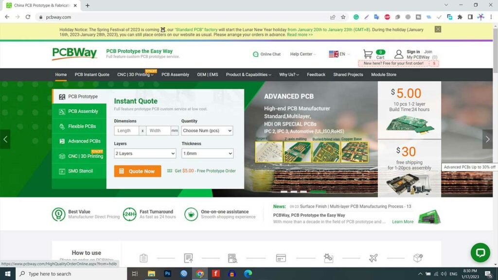
If you’re looking for a reliable and cost-effective PCB manufacturing partner, PCBWay is the way to go. With their unwavering commitment to quality, exceptional customer service, competitive pricing, and fast turnaround times, you can rest assured that your PCB project will be in safe hands. So, head over to PCBWay.com today and get started on your next project!
Arduino Code
This code is for controlling 8-16 relays using a DWIN touchscreen display and an Arduino. The code is written in C++ and is intended to run on any 5V-compatible Arduino microcontroller.
/* Relay ontrol system using Arduino & DWIN Display */
// https://iotprojectsideas.com //
#define DEBAG 1               // Debugging: 1 - on, 0 - off
const bool level = 0;         // 1 - high level relay, 0 - low level relay
const byte relays_num = 8;    // Number of relays
byte relays[relays_num] = {2, 3, 4, 5, 6, 7, 8, 9}; // Relay connection pins
//do not touch //
byte Buffer[20];     // Create buffer
byte Buffer_Len = 0;
bool flag = false;   // Data read flag from monitor

void setup() {
  if (DEBAG)
  {
    Serial.begin(115200);
    Serial.println("Start program");
  }
  for (byte i = 0; i < relays_num; i++)
  {
    pinMode(relays[i], OUTPUT);
    if (!level)
      digitalWrite(relays[i], HIGH);
  }

}

void loop() {
  ReadSerial();
}
void ReadSerial()
{
  if (Serial.available())
  {
    Buffer[Buffer_Len] = Serial.read();
    if (DEBAG)
    {
      Serial.print(Buffer[Buffer_Len], HEX);
      Serial.print(" ");
    }
    Buffer_Len++;
    flag = true;
  }
  else
  {
    if (flag)
    {
      if (Buffer[0] == 0X5A) {
        if (Buffer[4] == 0X50) {
          if (DEBAG)
          {
            Serial.println();
            Serial.println(Buffer[8], BIN);
          }
          for (byte i = 0; i < relays_num; i++)
          {
              digitalWrite(relays[i], level == 0 ? !bitRead(Buffer[8], i) : bitRead(Buffer[8], i));
          }

        }
      }
      Buffer_Len = 0; //Resetting the element number in an array
      flag = false;
    }
  }
}
Arduino Code Explanation
Certainly. Here is a line-by-line explanation of the Arduino code:
Defining Variables
In this program, various variables have been defined for various purposes. Here is an explanation of each variable and its purpose:
#define DEBAG 1 // Debugging: 1 - on, 0 - off
This code defines the DEBAG flag as a preprocessor directive. If DEBAG is set to 1, debugging is enabled, and if it is set to 0, debugging is disabled.
const bool level = 0; // 1 - high level relay, 0 - low level relay
This line defines the “level” constant as a boolean value. If “level” is set to 1, the relays are high level, and if it is set to 0, the relays are low level.
const byte relays_num = 8; // Number of relays
This line defines the “relays_num” constant as a byte value that specifies the number of relays being used.
byte relays[relays_num] = {2, 3, 4, 5, 6, 7, 8, 9}; // Relay connection pinsThis code defines the “relays” array as an array of bytes that stores the pin numbers for the relay connections.
byte Buffer[20]; // Create buffer
This line defines the “Buffer” array as an array of bytes that is used to store data read from the display.
byte Buffer_Len = 0;
It defines the “Buffer_Len” variable as a byte that stores the length of the “Buffer” array. It is initially set to 0.
bool flag = false; // Data read flag from monitor
This line defines the “flag” variable as a boolean that is used as a flag for reading data from the monitor. It is initially set to false.
Code in Void setup
void setup() {
  if (DEBAG)
  {
    Serial.begin(115200);
    Serial.println("Start program");
  }
  for (byte i = 0; i < relays_num; i++)
  {
    pinMode(relays[i], OUTPUT);
    if (!level)
      digitalWrite(relays[i], HIGH);
  }

}
This is the setup function, which is called once when the program starts. If the DEBAG flag is set to 1, the function initializes serial communication at a baud rate of 115200 and prints a message to the serial monitor. It then sets the pin modes for the relay connections to OUTPUT, and if the “level” variable is set to 0, it sets the initial state of the relays to HIGH.
Loop ReadSerial
void loop() {
  ReadSerial();
}
In the loop function, the code reads serial data and processes it using the ReadSerial function.
In Void ReadSerial
void ReadSerial()
{
  if (Serial.available())
  {
    Buffer[Buffer_Len] = Serial.read();
    if (DEBAG)
    {
      Serial.print(Buffer[Buffer_Len], HEX);
      Serial.print(" ");
    }
    Buffer_Len++;
    flag = true;
  }
  else
  {
    if (flag)
    {
      if (Buffer[0] == 0X5A) {
        if (Buffer[4] == 0X50) {
          if (DEBAG)
          {
            Serial.println();
            Serial.println(Buffer[8], BIN);
          }
          for (byte i = 0; i < relays_num; i++)
          {
              digitalWrite(relays[i], level == 0 ? !bitRead(Buffer[8], i) : bitRead(Buffer[8], i));
          }

        }
      }
      Buffer_Len = 0; //Resetting the element number in an array
      flag = false;
    }
  }
}
This is the “ReadSerial” function, which is called in the loop function. It reads data from the serial port and stores it in the “Buffer” array. If the DEBAG flag is set to 1, the system also prints the data in hexadecimal to the serial monitor. When there is no more data to read and the “flag” variable is true, it checks if the first byte in the “Buffer” array is 0X5A and the fifth byte is 0X50. If these conditions are met, the system reads the ninth byte in the “Buffer” array as a binary value and uses it to control the relays. The system then resets the “Buffer_Len” variable to 0 and sets the “flag” variable to false.
Uploading Program Code
To upload the program code to your Arduino board, you need to unplug the TX2 and RX2 pins from the DWIN Display. Then, select your Arduino board and the correct COM port in your Arduino IDE, and click the upload button to upload the code. You can connect TX2 and RX2 back once you have successfully uploaded the code.
Demonstration: Arduino and DWIN Display for Relay Control
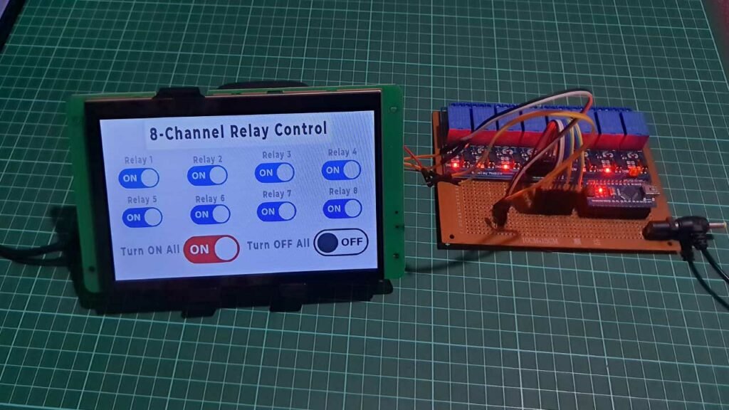
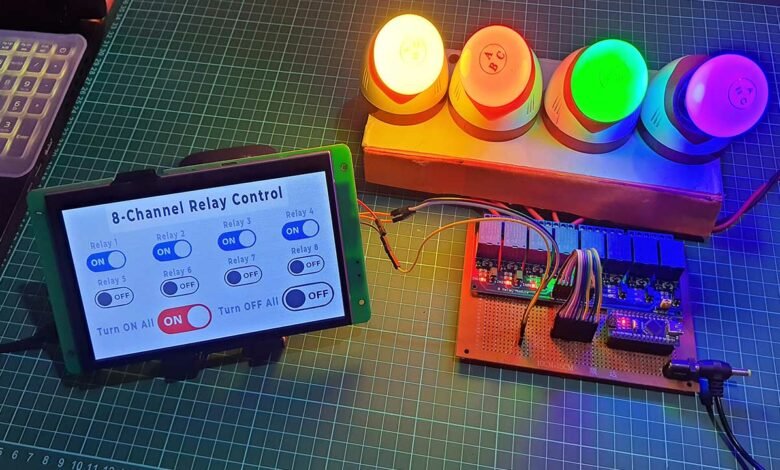
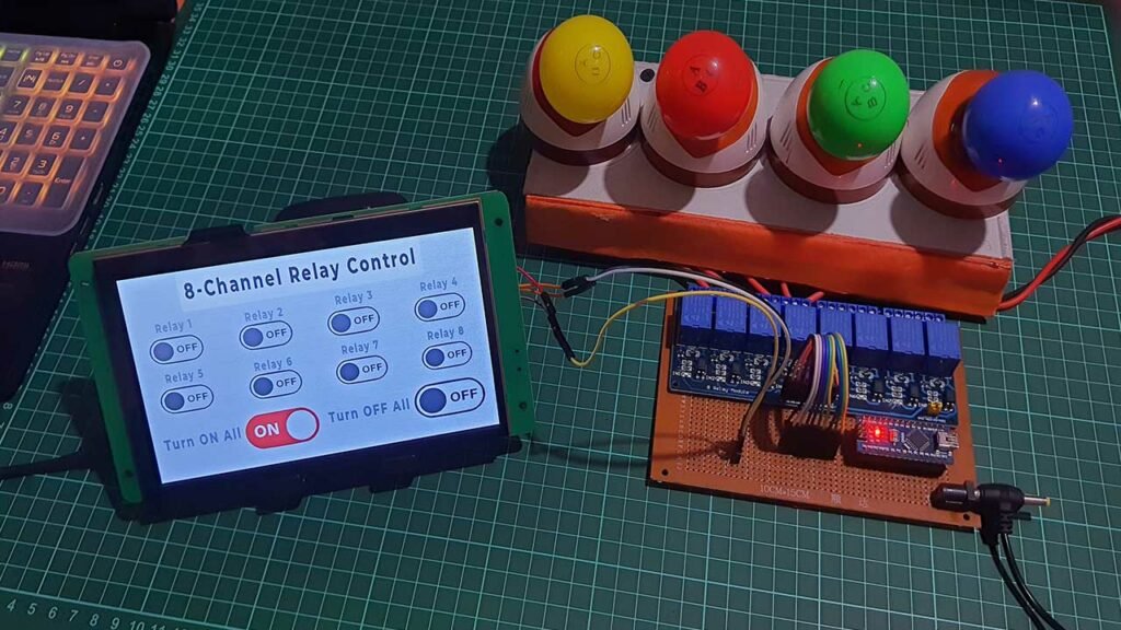
Now, you can use the user interface on the DWIN Display to control all eight of your relays.
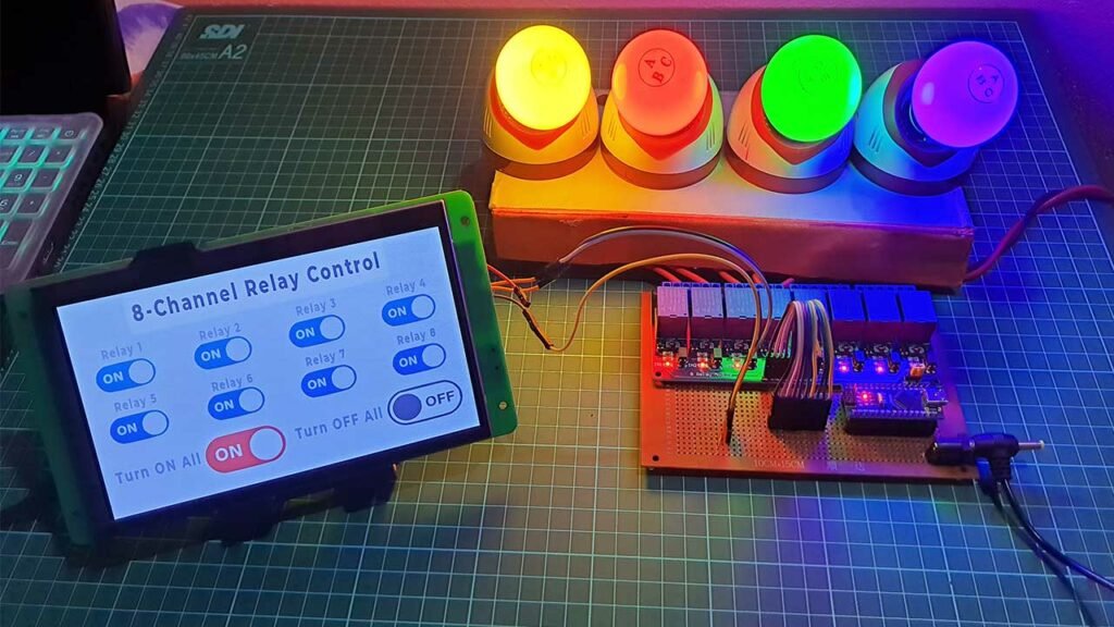
You can connect electrical devices such as lights, TVs, fans, heaters, etc. to the relays and control them using the touch display. For this demonstration, I am connecting four different light bulbs to relays 1, 2, 3, and 4. You can see real-time feedback on the display.
Conclusion
We have successfully created an 8-channel relay controller project using the DWIN HMI Display and Arduino. The user interface looks great on the display. I hope this tutorial was helpful to you. If it was, please don’t hesitate to like and share the project page with your friends.


Very nice tutorial, very well explained.
Please let me know how to implement radio buttons. Only one switch can be ON at a time, whereas all switched can be OFF. Thanks!
Hello, I have a question about the screen that you use in the article (dmg80480C070_07WTC). The documentation for it states that it runs on the T5L0 core, and for some reason you have the T5L1 core selected in the ICL Tools tab in the HSV program, why?
Hi , I’m connecting dwin HMI with Arduino Uno but unable to communicate with all proper connection and wiring and also made common ground.