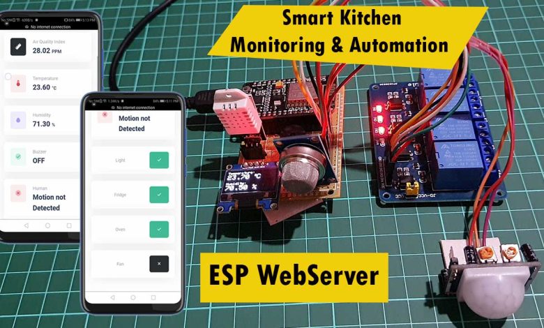
Overview: ESP8266 Based Smart Kitchen
In this project, we are going to build an ESP8266 based smart kitchen with automation and a monitoring system using ESP-DASH. The kitchen is an important part of the home for many families. Safety factors are the fundamental aspect that must be considered during the activity in the kitchen. The existence of gas leakage, uncontrolled fire, extreme temperature, and inhospitable environment should be identified and addressed as soon as possible. In addition, kitchen appliances such as lights, refrigerators, ovens, etc. need to be monitored and controlled remotely.
The main objective of this project is to build a prototype of ESP8266 based smart kitchen monitoring & automation system using a web server. The system uses multiple sensors, relays, and NodeMCU ESP8266 boards. We can monitor all sensor data graphically on the web dashboard. We can also send commands to control kitchen appliances from the webserver.
This ESP8266 based Smart Kitchen does the following tasks:
- Monitor the Kitchen Temperature & Humidity using DHT22 Sensor on the web dashboard.
- Monitor the Air Quality Index (Gas) using MQ-135 Gas Sensor on the web dashboard.
- Displays the Kitchen Temperature, Humidity & Gas Level on 0.96″ I2C OLED Display.
- The exhaust fan interfaced to Relay 4 turns ON & the Alarm activates once gas level exceeds.
- Detects the presence or absence of a person in the Kitchen using a PIR motion sensor.
- Sends Alarm Status, Exhaust Fan Status & Human Detection Status to the webserver.
- Users can turn ON/OFF Room lights, fridge, oven, etc. Remotely using buttons on a web dashboard.
Components Required
We will need a DHT22 Temperature and Humidity sensor to measure room humidity and temperature. MQ-135 Gas sensor to measure the gas leakage in the kitchen. A PIR sensor to detect the presence or absence of humans in the kitchen. We are using a simple 5V buzzer for alarm when the gas level exceeds. Similarly, 0.96″ I2C OLED Display for displaying Room temperature, humidity & Air Quality Index. We also have 4 channel relay modules to control the home appliances like lights, fridge, oven, heater, etc. Whereas relay 4 is connected to an exhaust fan which turns ON and OFF according to the gas level threshold value. The heart and brain of this project is a NodeMCU ESP8266 Board. But, you can use any of the ESP8266-12E based boards.
All the components are easily available on Amazon & you can purchase them easily from the following link.
| S.N | Components Name | Quantity | |
|---|---|---|---|
| 1 | NodeMCU ESP8266-12E Board | 1 | https://amzn.to/3sCrEbj |
| 2 | DHT22 Temperature & Humidity Sensor | 1 | https://amzn.to/32VEw1X |
| 3 | MQ-135 Gas Sensor | 1 | https://amzn.to/33kRE04 |
| 4 | 0.96" I2C OLED Display | 1 | https://amzn.to/3kvENyc |
| 5 | PIR Motion Sensor | 1 | https://amzn.to/3navcxS |
| 6 | 5V 4-Channel Relay Module | 1 | https://amzn.to/31Felf5 |
| 7 | 5V Small Buzzer | 1 | https://amzn.to/3I5qhXl |
| 8 | Few jumpers wires | 20 | https://amzn.to/3klh0A4 |
| 9 | Breadboard | 1 | https://amzn.to/3H2tbeQ |
System Design & working
We will use the sensors like DHT22 Temperature & Humidity Sensor, MQ-135 Gas Sensor, Passive Infrared (PIR) sensor to monitor the Indoor Air Quality Parameters. Similarly, a simple 5V buzzer is used for the alarming system. For automation, I connected an Exhaust Fan to a relay 4, which activates automatically when the gas level exceeds the defined threshold value.
Since we are using a 4 channel relay, we can connect the remaining 3 relays to kitchen appliances like Mixer, Refrigerator, Oven, Water Heater, Induction, etc. Using a simple 0.96 inch I2C OLED can Display we can monitor the room temperature, humidity, and gas value locally.
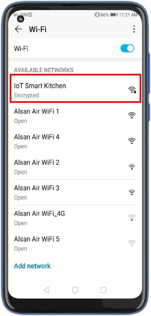
Since I’m configuring the ESP8266 Wi-Fi chip in Soft AP mode. So, you don’t need Wi-Fi or internet separately to monitor and control your appliances. The ESP8266 boards broadcast the “IoT Smart Kitchen” SSID. So, you need to connect to the Wi-Fi network using the password defined in the code. It establishes a connection with the NodeMCU ESP8266 board, and you can monitor those sensor values and control appliances remotely from the webserver.
Circuit Diagram connection/Schematic
Here is a simple circuit design using fritzing software. Use the following schematic as a reference and assemble the circuit on a breadboard.
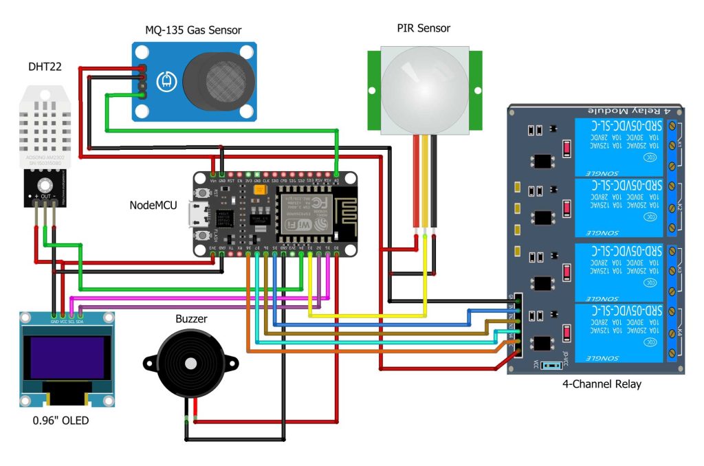
Connect the OLED Display SDA & SCL pins to NodeMCU D2 & D1 Pin. Similarly, connect the DHT11, MQ-135 & PIR Sensor output pin to the D4, A0 & D3 pin of NodeMCU. For the alarm system, you can connect the 5V active Buzzer to the D0 Pin. For controlling the Home Appliances, we can use a 4 channel Relay Module. So using the jumper wires, connect the 4 channel relay input pin to the D5, D6, D7 & D8 of NodeMCU ESP8266. MQ-135 sensor, PIR sensor & relay needs a 5V power supply. So connect VCC and GND pins to 5V and GND pins, respectively. Similarly, DHT22 & OLED Display VCC are connected to 3.3V pins of NodeMCU.
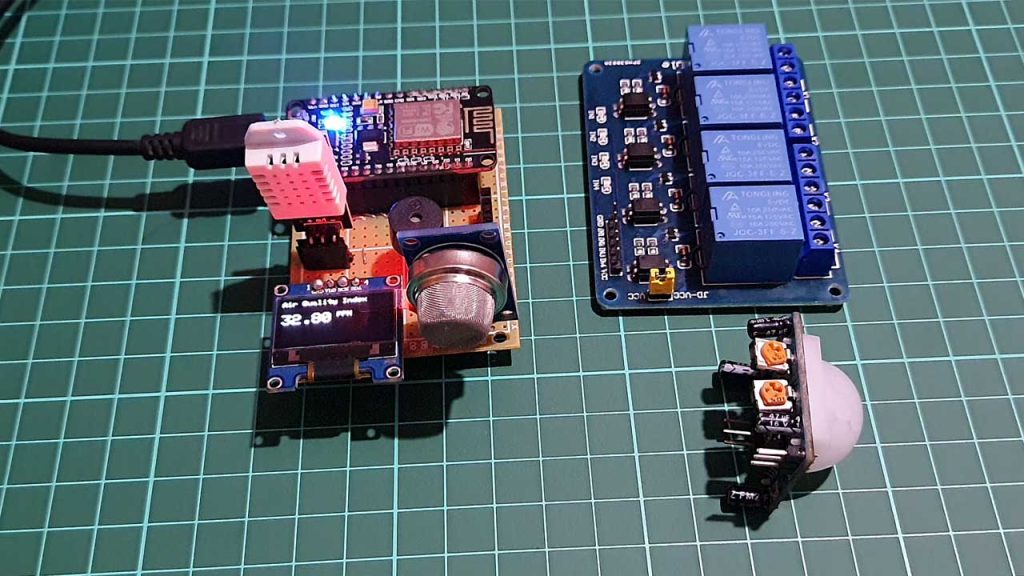
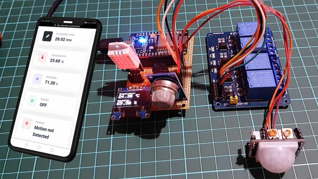
All the components are assembled as per the circuit diagram.
Project PCB Gerber File & PCB Ordering Online
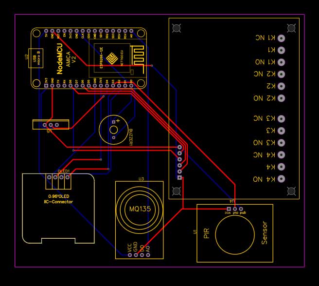
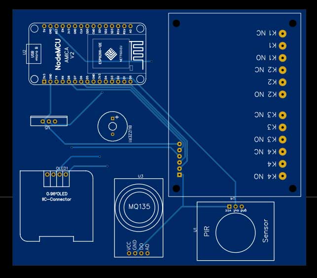
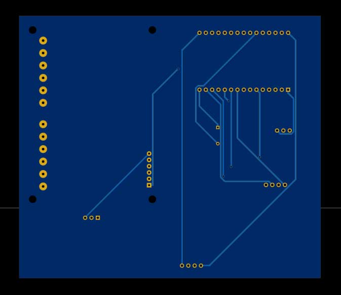
You can simply assemble the circuit on a breadboard. But To remove messy wiring and give a clean look, I designed a PCB prototype for this project. It is also helpful for troubleshooting without any errors. You can download the Gerber file of my PCB Design from the link attached below. The PCB looks like the image shown below.

I provided the Gerber File for ESP8266 Based Smart Kitchen Automation & Monitoring System PCB below.
You can simply download the Gerber File and order your custom PCB from PCBWay

Visit the PCBWay official website by clicking here: https://www.PCBWay.com/. Simply upload your Gerber File to the Website and place an order. I prefer PCBWay for ordering custom PCBs. PCBWay is a place that brings manufacturers and customers together. They have more than a decade of experience in this field of fabrication and prototyping and assembling of PCBs. PCBWay have proved their focus to their customers’ needs in terms of cost-effectiveness, delivery, and quality. And this can be proved by their outstanding customer reviews.
Source Code/Program: ESP8266 Smart Kitchen
This is the source code for ESP8266 Based Smart Kitchen Automation & Monitoring system with web dashboard. But before going for the code part, we need to add the following libraries to the Arduino IDE.
You can download these libraries from the link provided below or install them from Arduino IDE Library Manager.
- DHT Library: Download
- MQ-135 Library: Download
- Adafruit GFX Library: Download
- Adafruit SSD1306 Library: Download
- ESPAsyncWebServer Library: Download
- ESPAsyncTCP Library: Download
- ESP-DASH Library: Download
The main part of this web dashboard is the ESP-DASH library. It is a C ++ library for creating functional and real-time dashboards for ESP8266 and ESP32 microcontrollers. This makes it easier for you to use the functions and allows you to create an accessible dashboard to your module’s IP address.
After adding all these libraries, the code will compile easily. You can change the Wi-Fi SSID, and Password if you need through this code.
/* Your Soft AP WiFi Credentials */
const char *ssid = "IoT Smart Kitchen"; // WiFi Name
const char* password = "1234567890"; // Password
This is a complete code for the project. Paste this code on the Arduino IDE. Then select the NodeMCU ESP8266 board from the Board manager & also select the COM port and upload the code.
/*
  -----------------------
  Smart Kitchen Monitoring & Automation using ESP8266
  -----------------------
  Website: https://iotprojectsideas.com/
  -----------------------

*/

#include <Arduino.h>
#include <ESP8266WiFi.h>
#include <ESPAsyncTCP.h>
#include <ESPAsyncWebServer.h>
#include <ESPDash.h>
#include <SPI.h>
#include <Wire.h>
#include "MQ135.h"
#include <Adafruit_Sensor.h>
#include <DHT.h>
#include <Adafruit_GFX.h>
#include <Adafruit_SSD1306.h>

/* Your Soft AP WiFi Credentials */
const char *ssid = "IoT Smart Kitchen"; // WiFi Name
const char* password = "1234567890"; // Password

#define SCREEN_WIDTH 128    // OLED display width, in pixels
#define SCREEN_HEIGHT 64    // OLED display height, in pixels
#define OLED_RESET -1       // Reset pin # (or -1 if sharing Arduino reset pin)

#define DHTTYPE DHT22     // DHT 22
#define DHTPIN D4 //DHT22 Pin D4(GPIO 2)

#define relay1 D5 // Light D5(GPIO 14)
#define relay2 D6 //Fridge D6(GPIO 12)
#define relay3 D7 // Oven D7(GPIO 13)
#define relay4 D8 // Fan D8(GPIO 15)

#define buzzer D0 //Buzzer Pin D0(GPIO 16)
#define PIR D3 //PIR Sensor Pin D3(GPIO 0)


int alarm_status;
int pir_status = 0;

DHT dht(DHTPIN, DHTTYPE);
Adafruit_SSD1306 display(SCREEN_WIDTH, SCREEN_HEIGHT, &Wire, OLED_RESET);

/* Start Webserver */
AsyncWebServer server(80);

/* Attach ESP-DASH to AsyncWebServer */
ESPDash dashboard(&server);
/*
  Dashboard Cards
  Format - (Dashboard Instance, Card Type, Card Name, Card Symbol(optional) )
*/
Card AIQ(&dashboard, GENERIC_CARD, "Air Quality Index", "PPM");
Card temperature(&dashboard, TEMPERATURE_CARD, "Temperature", "°C");
Card humidity(&dashboard, HUMIDITY_CARD, "Humidity", "%");
Card light(&dashboard, BUTTON_CARD, "Light");
Card fridge(&dashboard, BUTTON_CARD, "Fridge");
Card oven(&dashboard, BUTTON_CARD, "Oven");
Card fan(&dashboard, BUTTON_CARD, "Fan");
Card Buzzer(&dashboard, STATUS_CARD, "Buzzer");
Card Motion_PIR(&dashboard, STATUS_CARD, "Human");

void setup() {
  Serial.begin(115200);

  /* Connect WiFi */
  WiFi.softAP(ssid, password);
  Serial.print("IP address: ");
  Serial.println(WiFi.softAPIP());
  /* Start AsyncWebServer */
  server.begin();

  dht.begin();
  display.begin(SSD1306_SWITCHCAPVCC, 0x3C); //initialize with the I2C addr 0x3C (128x64)

  pinMode(PIR, INPUT);
  pinMode(buzzer, OUTPUT);
  pinMode(relay1, OUTPUT);
  pinMode(relay2, OUTPUT);
  pinMode(relay3, OUTPUT);
  pinMode(relay4, OUTPUT);

  digitalWrite(buzzer, LOW);
  digitalWrite(relay1, HIGH);
  digitalWrite(relay2, HIGH);
  digitalWrite(relay3, HIGH);
  digitalWrite(relay4, HIGH);
  delay(100);
}

void loop() {
  /* Update Card Values */
   MQ135 gasSensor = MQ135(A0);
  float air_quality = gasSensor.getPPM();

  float t = dht.readTemperature();
  float h = dht.readHumidity();

  pir_status = digitalRead(PIR);
  alarm_status = digitalRead(buzzer);


  if (pir_status == 1)
  {
    Serial.println("Motion Detected");
    Motion_PIR.update("Motion Detected", "success");
    dashboard.sendUpdates();
  }
  else if (pir_status == 0)
  {
    Serial.println("Motion not Detected");
    Motion_PIR.update("Motion not Detected", "danger");
    dashboard.sendUpdates();
  }


  if (air_quality > 150)
  {
    digitalWrite(buzzer, HIGH);
    digitalWrite(relay4, LOW);
    Serial.println("Buzzer Status: ON");
    Serial.println("Exhaust Fan: ON");
    Buzzer.update("ON", "warning");
    fan.update(HIGH);
    dashboard.sendUpdates();
  }
  else
  {
    digitalWrite(buzzer, LOW);
    digitalWrite(relay4, HIGH);
    Serial.println("Buzzer Status: OFF");
    Serial.println("Exhaust Fan: OFF");
    Buzzer.update("OFF", "success");
    fan.update(LOW);
    dashboard.sendUpdates();
  }

  Serial.print("Air Quality: ");
  Serial.print(air_quality);
  Serial.println(" PPM");

  Serial.print("Temperature: ");
  Serial.print(t);
  Serial.println(" *C");

  Serial.print("Humidity: ");
  Serial.print(h);
  Serial.println(" %");

  Serial.println();
  Serial.println("****************************");
  Serial.println();


  temperature.update(t);
  humidity.update(h);
  AIQ.update(air_quality);
  //Button for Light
  light.attachCallback([&](bool value){
  Serial.println("[light] Button Callback Triggered: "+String((value)?"HIGH":"LOW"));
  digitalWrite(relay1, (value));
  light.update(value);
  dashboard.sendUpdates();
});
//Button for Fridge
  fridge.attachCallback([&](bool value){
  Serial.println("[fridge] Button Callback Triggered: "+String((value)?"HIGH":"LOW"));
  digitalWrite(relay2, (value));
  fridge.update(value);
  dashboard.sendUpdates();
});
//Button for Oven
  oven.attachCallback([&](bool value){
  Serial.println("[oven] Button Callback Triggered: "+String((value)?"HIGH":"LOW"));
   digitalWrite(relay3, (value));
  oven.update(value);
  dashboard.sendUpdates();
});
//Button for Fan
  fan.attachCallback([&](bool value){
  Serial.println("[fan] Button Callback Triggered: "+String((value)?"HIGH":"LOW"));
  digitalWrite(relay4, (value));
  fan.update(value);
  dashboard.sendUpdates();
});
  /* Send Updates to our Dashboard (realtime) */
  dashboard.sendUpdates();
  delay(1500);

  display.clearDisplay();
  display.setCursor(0, 0); //oled display
  display.setTextSize(1);
  display.setTextColor(WHITE);
  display.println("Air Quality Index");

  display.setCursor(0, 20); //oled display
  display.setTextSize(2);
  display.setTextColor(WHITE);
  display.print(air_quality);
  display.setTextSize(1);
  display.setTextColor(WHITE);
  display.println(" PPM");
  display.display();
  delay(1500);

  display.clearDisplay();

  // display temperature
  display.setTextSize(1);
  display.setCursor(0, 0);
  display.print("Temperature: ");
  display.setTextSize(2);
  display.setCursor(0, 10);
  display.print(t);
  display.print(" ");
  display.setTextSize(1);
  display.cp437(true);
  display.write(167);
  display.setTextSize(2);
  display.print("C");

  // display humidity
  display.setTextSize(1);
  display.setCursor(0, 35);
  display.print("Humidity: ");
  display.setTextSize(2);
  display.setCursor(0, 45);
  display.print(h);
  display.print(" %");

  display.display();
  delay(1500);
}
Testing of IoT Smart Kitchen Project
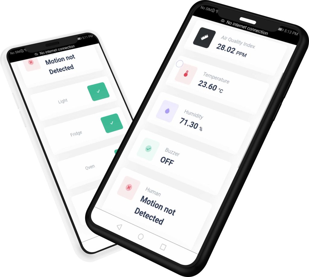
After uploading the code, the NodeMCU ESP8266 Board broadcasts the Wi-Fi network “IoT Smart Kitchen”. Connect your Mobile/laptop to this network using the password defined in the code. After a successful connection, open the following IP address (192.168.4.1) on your preferred web browser. The ESP Dashboard will load successfully. Now, you can monitor sensor data and control appliances through this beautiful web dashboard.
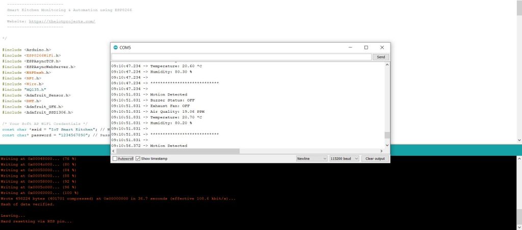
Meanwhile, you can open the Serial Monitor as well. The Serial Monitor will display the Humidity, Temperature, Air Quality Index, Alarm Status, Human Detection, etc.
On the other hand, the OLED Display will display the Temperature, Humidity & Gas Level of the Kitchen.
The webserver will get new data asynchronously every 1500 milliseconds from NodeMCU. The Temperature, Humidity & Air Quality Index Data are displayed graphically. It will also show whether the Buzzer is ON or OFF as well as the presence of humans inside the room or not.
Relay 4 that connects to the exhaust fan automatically activates when the Gas level reaches the threshold value. I set the threshold value to 150 PPM. You can set it to any desired value. You can send the command from the web dashboard to turn ON & OFF the Kitchen Appliances like Fridge, Oven & lights.
This is how you can design your own ESP8266 NodeMCU Based Smart Kitchen using ESP-DASH with Automation & Monitoring System on a web server.


Quite comprehensive tutorial… Awesome! I wonder if you can try to connect to our Favoriot IoT platform? It’s free to trial. Appreciate your kind feedback. We will share any projects on our social media that uses our IoT platform. Thanks!!
Sure I will try your IoT platform.
Thanks Alsan
CAN U HELP ME
Yes I can help you
Hallo mas alsan. saya penasaran apakah monitoring dari sistem ini bisa menggunakan mobile app bukan menggunakan server web?
Hello i tried to make it work, but not work, i installed all librarys,and copy and paste the code
comprehensive tutorial… Awesome! it can work in different network that means the esp8266 and the smart phone on different network? thanks
I’m not at all good at programming, I would simply like to view the data of the dht11 sensor and the mq135 sensor on the display, without connection to a webserver or anything else, who can help me to clean up the code of what is not needed? Thank you