Arduino Based GSM Mobile Phone using SIM800L
Simple Phone: Call & SMS using GSM Module & Arduino
Overview: Arduino Mobile Phone using SIM800L
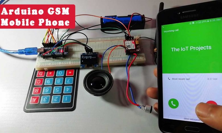
In this post, you will learn to make your own Arduino based GSM Mobile Phone using the SIM800L module. We work on different projects and sometimes find it very difficult to use the GSM module to make a call or SMS with microcontrollers. So here I am going to make a simple homemade mobile phone using Arduino, Keypad, OLED Display, and GSM SIM800L Module. GSM Module is used to make calls, receive calls. Similarly, it can be used to send an SMS as well as read a received SMS. Mic and Speaker used on this Arduino based Phone make it possible to talk to each other as a normal phone.
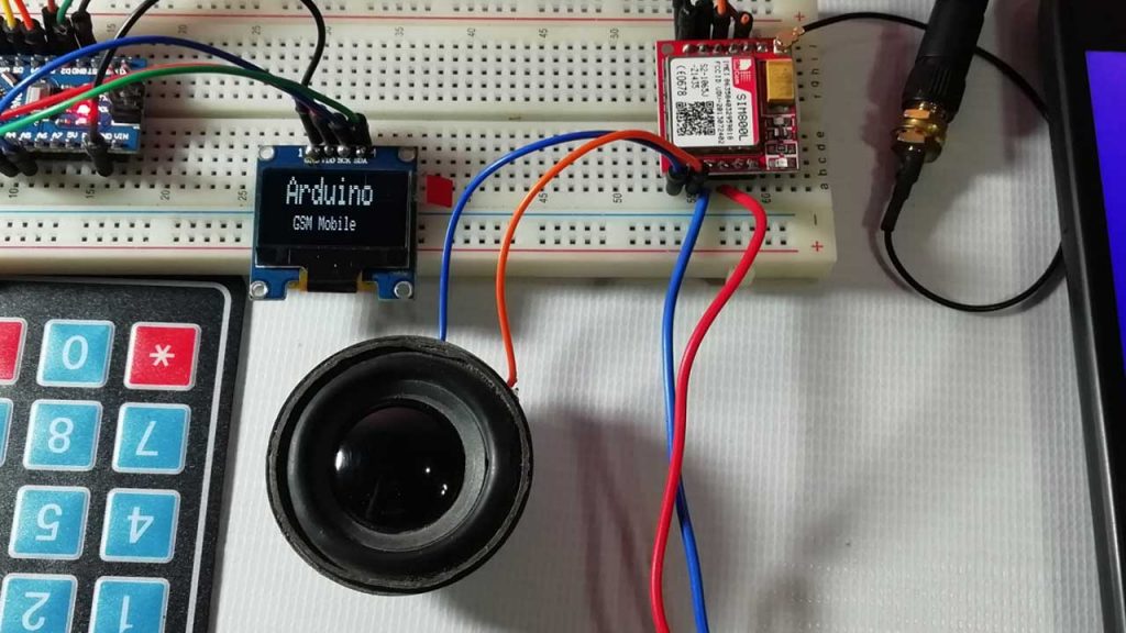
Here, you will learn the proper interfacing of the GSM Module with Arduino and Program it to perform the basic function of mobile phones. So I have interfaced GSM Module SIM800L with Arduino Nano Board. An SSD1306 OLED Display is used for displaying the operations like incoming or outgoing calls, SMS sent and received status, etc. The 4×4 Keypad is used to enter the number or type an SMS text. the speaker is used for ringing and listening to incoming calls and Mic is used to transmit the spoken sound.
The Advanced Version of this Project is available here: Nextion Display based GSM Mobile phone using Arduino.
Components Required
This simple Arduino based phone is very useful for final year projects and also for understanding the basic functionality of the GSM module using AT Commands. All the components required for making this project can be purchased from the link given below.
| S.N | Components Name | Quantity | |
|---|---|---|---|
| 1 | Arduino Nano | 1 | https://amzn.to/2Ym97CW |
| 2 | GSM SIM800L Module | 1 | https://amzn.to/3jMdsHV |
| 3 | 4x4 Keypad | 1 | https://amzn.to/38JmkrG |
| 4 | Small Speaker | 1 | https://amzn.to/2YwaW0n |
| 5 | Condenser Mic | 1 | https://amzn.to/3h6pslH |
| 6 | Few jumpers wires | 20 | https://amzn.to/3klh0A4 |
| 7 | 3.7V 18650 holder with battery | 1 | https://amzn.to/3BJovrt |
| 8 | Breadboard | 1 | https://amzn.to/3mt0O2c |
Working of Arduino Mobile Phone
In this Arduino based Mobile Phone Project, we have used Arduino Nano to control the whole system. A 4×4 Alphanumeric Keypad is used for entering mobile numbers, type messages, make a call, receive a call, send SMS, and read SMS. GSM Module communicates with the network for calling and texting purposes. I also added a MIC and a Speaker for Voice calls. An OLED display is used for showing instructions.
Alphanumeric is a method for entering both numbers and alphabets by using the same keypad. So the working of this project is very easy to understand. All the features will be regulated by using a 4×4 Keypad.
Features of Arduino GSM Phone
Here I am going to explain the four basic features of this homemade mobile phone.
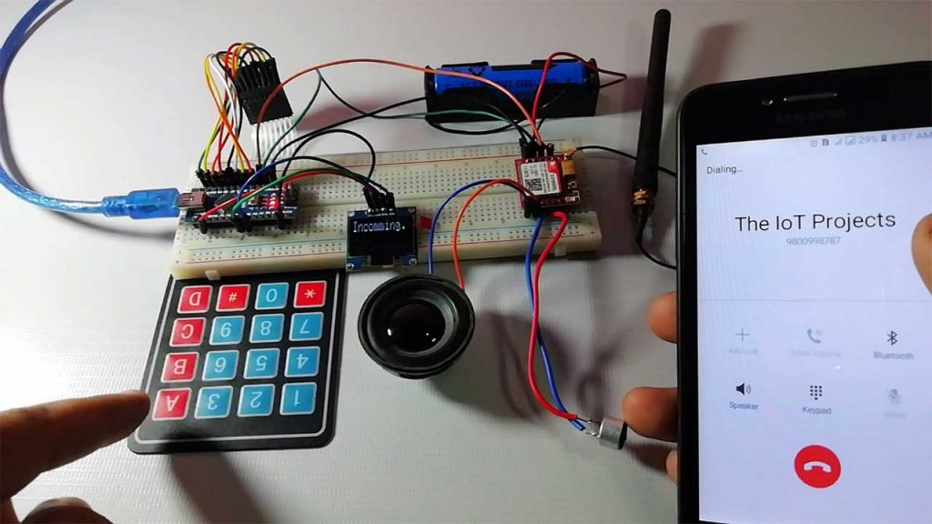
1. Make a Call:
To make a call using this Arduino based Phone, you have to press ‘C’ and then need to enter the Mobile Number on which you want to make a call. The number will be entered by using an alphanumeric keypad. After entering the number again press ‘C’. Now Arduino will process for connecting the call to the entered number by using AT command:
ATDxxxxxxxxxx; <Enter> where xxxxxxxxx is entered Mobile Number.
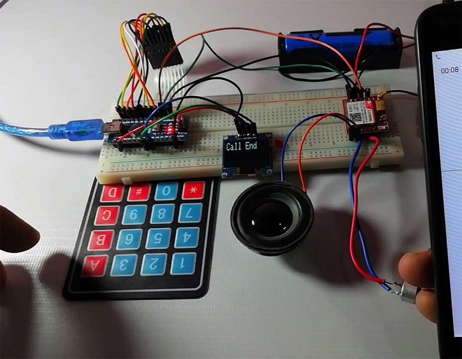
‘C’: Call on the dialed number
‘D’:used to cancel calling operation
‘*’:used to delete a printed digit
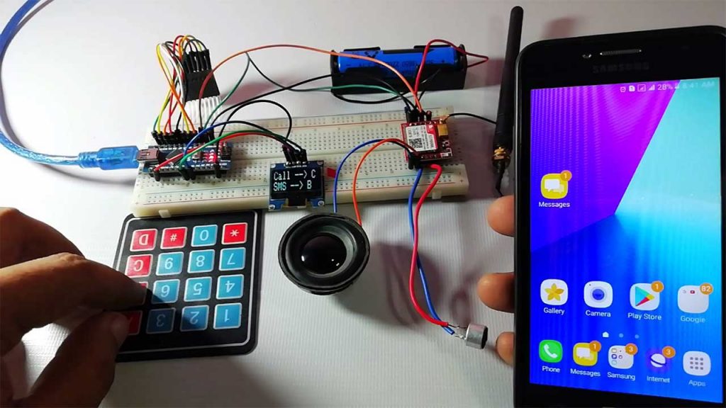
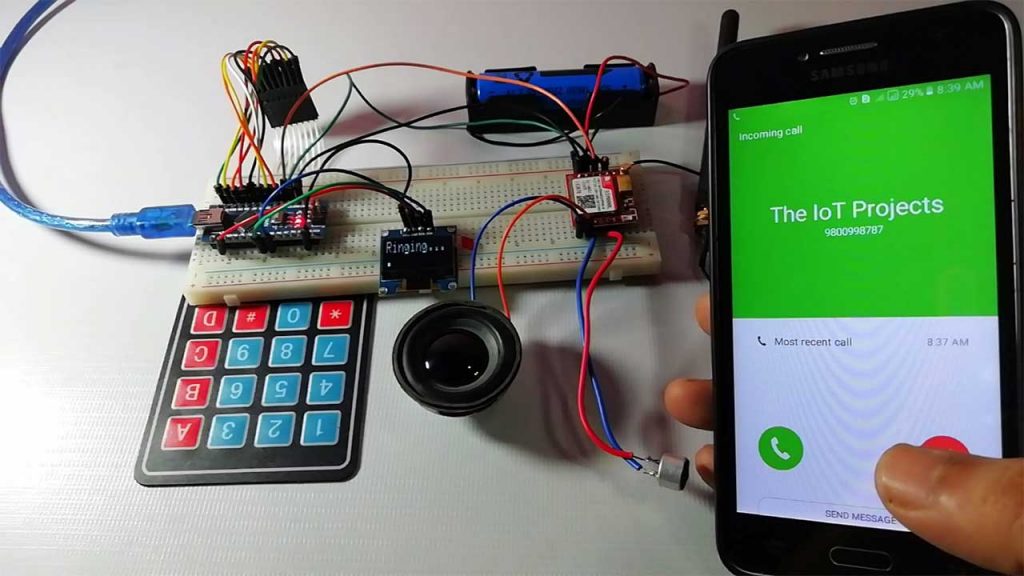
2. Receive a Call:
Receiving a call is very easy. When someone calls your number, which is inserted in GSM Module. The system will show an ‘Incoming…’ message on the OLED display with the incoming number of callers. Now we just need to Press ‘A’ to attend the call. When we press ‘A’, Arduino will send the given command to GSM Module:
ATA <enter>
‘A’: used to Pick up Call.
‘D: used to halt or terminate Call
3. Send SMS:
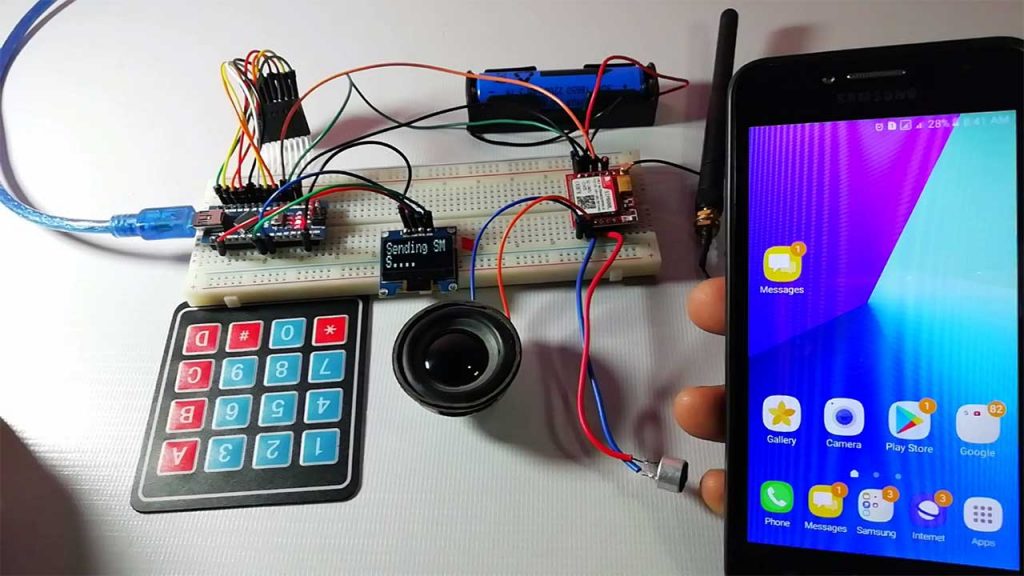
When you want to send an SMS using this Arduino based Mobile Phone, you need to Press ‘B’. Now System will ask for the Recipient Number. which means ‘to whom you want to send an SMS. After entering the number you need to press ‘D’ and now Display asks for your message. You need to type your message. using a keypad. Then after entering the message press ‘D’ to send SMS. To Send SMS Arduino sends the given command:
These buttons are also used in Send message mode.
‘B’: Used to initialize SMS operation
‘*’: Used to delete a printed digit
‘D’: Send SMS on the dialed number
AT+CMGF=1 <enter>
AT+CMGS=”xxxxxxxxxx” <enter>     where: xxxxxxxxxx is entered mobile number
4. Receive and Read SMS:
Reading received SMS is also simple. You just need to Press ‘D’, to read the SMS, when receiving a New Message. Below is the SMS Received indication on the Serial port:
+CMTI: “SM” <SMS stored location>
+CMTI: “SM”,6  Where 6 is message location where it stored in SIM card.
When Arduino gets this ‘SMS received’ indication. It extracts SMS storing location and sends commands to GSM to read the received SMS.
AT+CMGR=<SMS stored location><enter>
AT+CMGR=6
Note: Here we don’t need any coding for MIC and Speaker as they are directly connected to GSM Module..
Circuit Diagram and Explanation:
The Circuit Diagram of Arduino based GSM Mobile phone using SIM800L, Keypad, Mic, and speaker is given below:
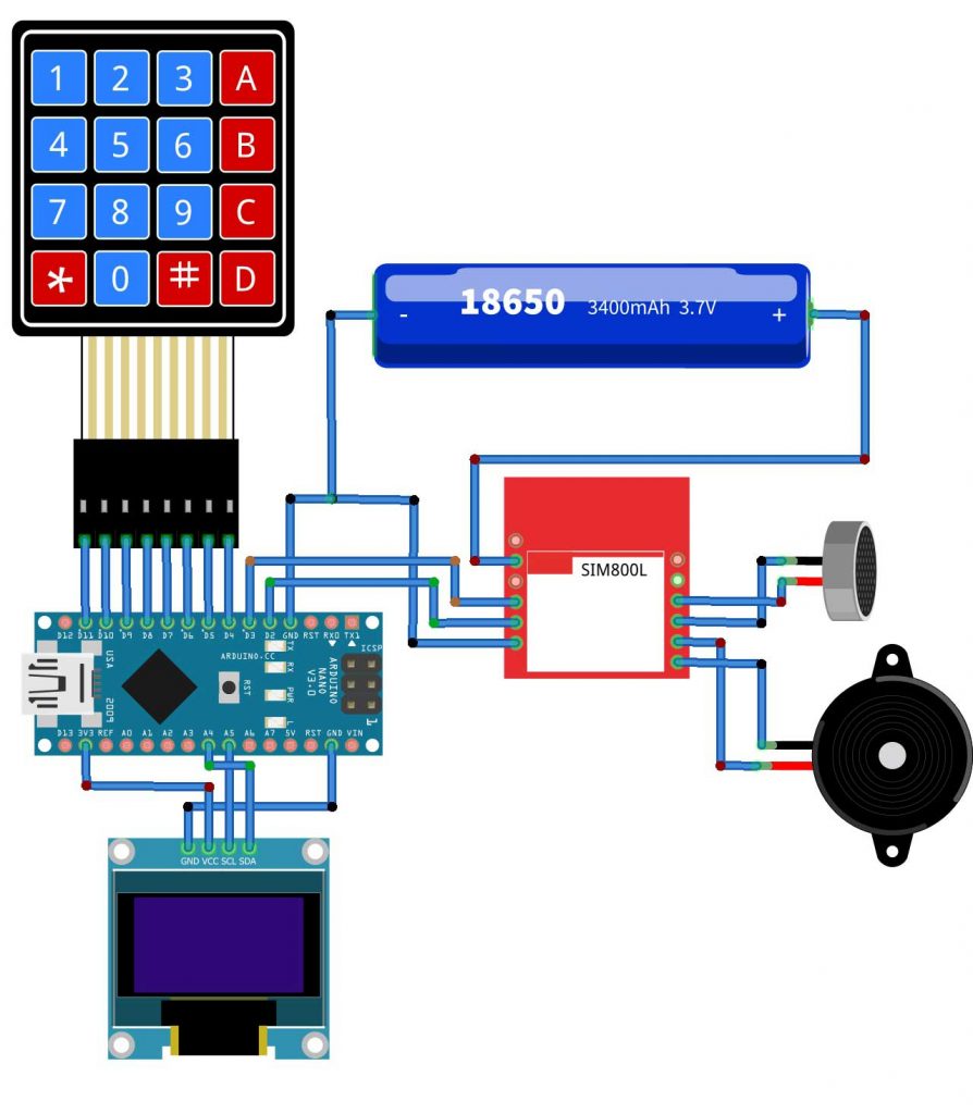
| Arduino Nano | GSM SIM800L Module |
| D2 | Tx |
| D3 | Rx |
| Arduino Nano | Keypad |
| D11 | R1 |
| D10 | R2 |
| D9 | R3 |
| D8 | R4 |
| D7 | C1 |
| D6 | C2 |
| D5 | C3 |
| D4 | C4 |
| MIC | SIM800L |
| Positive | Mic+ |
| Negative | Mic- |
| Speaker | SIM800L |
| Positive | S+ |
| Negative | S- |
| Arduino Nano | OLED Display |
| A5 | SCL |
| A4 | SDA |
| VCC | 3.3V |
| GND | GND |
| 18650 Battery | GSM Module |
| Positive | VCC |
| Negative | GND |
The SCL and SDA I2C pins of SSD1306 Display are connected to A5 and A4 pin of Arduino Nano respectively. While Vcc is connected to 3.3V and Ground pin to GND pin. Similarly, GSM Module’s Rx and Tx pins are directly connected with Arduino’s pin D3 and D2. 4×4 keypad Row pins R1, R2, R3, R4 are interfaced to pin numbers 11,10, 9, 8 of Arduino, and Column pins of keypad C1, C2, C3, and C4 are linked with pin numbers 7, 6, 5, 4 of Arduino Nano. MIC and Speaker are directly interfaced to mic+, mic- and SP+, SP- pins for GSM Module.
PCBWay PCB Prototyping Services
I have assembled the whole circuit on a breadboard. As you know breadboard assembly is not effective for this type of projects. So, PCBWay offers Rapid PCB Prototyping for Your Research Work. I personally, recommend PCBWay because you can get your first-try boards right in 24 hours!

The prototyping stage is the most critical period of time for engineers, students, and hobbyists. PCBWay not only makes your boards quick but also makes your job right as well as cost-effective. This greatly reduces your cost and shortens the time for developing your electronic products.
PCBWay can provide 2 Layer PCBs to highly advanced HDI and flex boards. Even though the PCBs they produce differ a lot regarding functionality and areas of use. I am impressed with the quality of the boards, the delivery time, and the cost-effectiveness.
Arduino Phone Program Code
The source code/program of this project is complex for beginners. In this code, I have used the keypad library, Adafruit SSD1306 library, Adafruit GFX Library, etc. The Keypad library is used for interfacing a simple 4×4 keypad for entering numbers and alphabets.
Like if we press key 2 (abc2). It will print ‘a’ and if we press it again then it will replace ‘a’ with ‘b’, Similarly, if we press three times then it will show ‘c’ in OLED Display. If we wait for a second after pressing a key, the cursor will automatically move to the next position in Display. Now we can enter the next character or number. The same procedure is applied for other keys.
Apart from an operating keypad, there are many other functions like void call() for calling feature of Phone, void SMS() for messaging feature, void lcd_status() for display status void gsm_init() for initializing the GSM Module, etc.
#include <SoftwareSerial.h>
#include <Adafruit_GFX.h>
#include <Adafruit_SSD1306.h>
SoftwareSerial Serial1(2, 3); // RX, TX
#define OLED_RESET 4
Adafruit_SSD1306 display(OLED_RESET);
byte back[8] =
{
0b00000,
0b00000,
0b11111,
0b10101,
0b11011,
0b11111,
0b00000,
0b00000
};
String number="";
String msg="";
String instr="";
String str_sms="";
String str1="";
int ring=0;
int i=0,temp=0;
int sms_flag=0;
char sms_num[3];
int rec_read=0;
int temp1=0;
#include <Keypad.h>
const byte ROWS = 4; //four rows
const byte COLS = 4; //four columns
char hexaKeys[ROWS][COLS] =
{
{'1','2','3','A'},
{'4','5','6','B'},
{'7','8','9','C'},
{'*','0','#','D'}
};
byte rowPins[ROWS] = {11, 10, 9, 8}; //connect to the row pinouts of the keypad
byte colPins[COLS] = {7, 6, 5, 4}; //connect to the column pinouts of the keypad
//initialize an instance of class NewKeypad
Keypad customKeypad = Keypad( makeKeymap(hexaKeys), rowPins, colPins, ROWS, COLS);
String ch="1,.?!@abc2def3ghi4jkl5mno6pqrs7tuv8wxyz90 ";
void setup()
{
display.begin(SSD1306_SWITCHCAPVCC, 0x3C);
Serial1.begin(9600);
display.clearDisplay();
display.display();
display.setTextColor(WHITE); // or BLACK);
display.setTextSize(2);
display.setCursor(18,0);
display.print("Arduino ");
display.setTextSize(1);
display.setCursor(20,20);
display.print(" GSM Mobile ");
display.display();
delay(1500);
gsm_init();
display.display();
display.setTextColor(WHITE); // or BLACK);
display.setTextSize(2);
display.setCursor(15,0);
display.print("System");
display.setCursor(20,18);
display.print("Ready");
display.display();
delay(2000);
}
void loop()
{
serialEvent();
if(sms_flag==1)
{
display.clearDisplay();
display.display();
display.setTextColor(WHITE); // or BLACK);
display.setTextSize(2);
display.setCursor(10,0);
display.print("New Message");
display.display();
int ind=instr.indexOf("+CMTI: "SM",");
ind+=12;
int k=0;
display.display();
display.setTextSize(1);
display.setCursor(0,20);
display.print(ind);
display.display();
while(1)
{
while(instr[ind]!= 0x0D)
{
sms_num[k++]=instr[ind++];
}
break;
}
ind=0;
sms_flag=0;
display.clearDisplay();
display.display();
display.setTextSize(1);
display.setCursor(0,20);
display.print("Read SMS --> D");
display.display();
delay(4000);
instr="";
rec_read=1;
temp1=1;
i=0;
}
if(ring == 1)
{
number="";
int loc=instr.indexOf("+CLIP: "");
if(loc > 0)
{
number+=instr.substring(loc+8,loc+13+8);
}
display.clearDisplay();
display.display();
display.setTextColor(WHITE); // or BLACK);
display.setTextSize(2);
display.setCursor(0,0);
display.print("Incomming...");
display.setTextSize(1);
display.setCursor(0,18);
display.print(number);
display.display();
instr="";
i=0;
}
else
{
serialEvent();
display.clearDisplay();
display.display();
display.setTextColor(WHITE); // or BLACK);
display.setTextSize(2);
display.setCursor(0,0);
display.print("Call --> C");
display.setTextSize(2);
display.setCursor(0,18);
display.print("SMS --> B");
display.display();
if(rec_read==1)
{
display.clearDisplay();
display.display();
display.setTextColor(WHITE); // or BLACK);
display.setTextSize(2);
display.setCursor(10,0);
display.print(" ");
}
else
display.print(" ");
}
char key=customKeypad.getKey();
if(key)
{
if(key== 'A')
{
if(ring==1)
{
Serial1.println("ATA");
delay(5000);
}
}
else if(key=='C')
{
call();
}
else if(key=='B')
{
sms();
}
else if(key == 'D' && temp1==1)
{
rec_read=0;
display.clearDisplay();
display.display();
display.setTextColor(WHITE); // or BLACK);
display.setTextSize(2);
display.setCursor(0,0);
display.print("Please wait...");
display.display();
Serial1.print("AT+CMGR=");
Serial1.println(sms_num);
int sms_read_flag=1;
str_sms="";
while(sms_read_flag)
{
while(Serial1.available()>0)
{
char ch=Serial1.read();
str_sms+=ch;
if(str_sms.indexOf("OK")>0)
{
sms_read_flag=0;
//break;
}
}
}
int l1=str_sms.indexOf(""rn");
int l2=str_sms.indexOf("OK");
String sms=str_sms.substring(l1+3,l2-4);
display.clearDisplay();
display.display();
display.setTextColor(WHITE); // or BLACK);
display.setTextSize(2);
display.setCursor(0,0);
display.print(sms);
display.display();
delay(5000);
}
delay(1000);
}
}
void call()
{
number="";
display.clearDisplay();
display.display();
display.setTextColor(WHITE); // or BLACK);
display.setTextSize(2);
display.setCursor(0,0);
display.print("After Enter No.");
delay(2000);
display.clearDisplay();
display.display();
display.setTextColor(WHITE); // or BLACK);
display.setTextSize(2);
display.setCursor(0,0);
display.print("Enter Number:");
display.setTextSize(1);
display.setCursor(0,18);
while(1)
{
serialEvent();
char key=customKeypad.getKey();
if(key)
{
if(key=='C')
{
display.clearDisplay();
display.display();
display.setTextColor(WHITE); // or BLACK);
display.setTextSize(2);
display.setCursor(0,0);
display.print("Calling...");
display.setTextSize(1);
display.setCursor(0,18);
display.print(number);
display.display();
Serial1.print("ATD");
Serial1.print(number);
Serial1.println(";");
long stime=millis()+5000;
int ans=1;
while(ans==1)
{
while(Serial1.available()>0)
{
if(Serial1.find("OK"))
{
display.clearDisplay();
display.display();
display.setTextColor(WHITE); // or BLACK);
display.setTextSize(2);
display.setCursor(0,0);
display.print("Ringing....");
display.display();
int l=0;
str1="";
while(ans==1)
{
while(Serial1.available()>0)
{
char ch=Serial1.read();
str1+=ch;
if(str1.indexOf("NO CARRIER")>0)
{
display.clearDisplay();
display.display();
display.setTextColor(WHITE); // or BLACK);
display.setTextSize(2);
display.setCursor(0,0);
display.print("Call End");
display.display();
delay(2000);
ans=0;
return;
}
}
char key=customKeypad.getKey();
if(key == 'D')
{
display.clearDisplay();
display.display();
display.setTextColor(WHITE); // or BLACK);
display.setTextSize(2);
display.setCursor(0,0);
display.print("Call End");
display.display();
delay(2000);
ans=0;
return;
}
if(ans==0)
break;
}
}
}
}
}
else
{
number+=key;
display.clearDisplay();
display.display();
display.setTextColor(WHITE); // or BLACK);
display.setTextSize(2);
display.setCursor(0,0);
display.print(key);
display.display();
}
}
}
}
void sms()
{
display.clearDisplay();
display.display();
display.setTextColor(WHITE); // or BLACK);
display.setTextSize(2);
display.setCursor(0,0);
display.print("Initilising SMS");
display.display();
Serial1.println("AT+CMGF=1");
delay(2000);
display.clearDisplay();
display.display();
display.setTextColor(WHITE); // or BLACK);
display.setTextSize(2);
display.setCursor(0,0);
display.print("Enter Rcpt No.:");
display.setTextSize(1);
display.setCursor(0,18);
display.display();
Serial1.print("AT+CMGS="");
while(1)
{
serialEvent();
char key=customKeypad.getKey();
if(key)
{
if(key=='D')
{
//number+='"';
Serial1.println(""");
break;
}
else
{
//number+=key;
Serial1.print(key);
display.clearDisplay();
display.display();
display.setTextColor(WHITE); // or BLACK);
display.setTextSize(2);
display.setCursor(0,0);
display.print(key);
display.display();
}
}
}
Serial1.print("key");
display.clearDisplay();
display.display();
display.setTextColor(WHITE); // or BLACK);
display.setTextSize(2);
display.setCursor(0,0);
display.print("Press D to Send ");
display.display();
delay(2000);
display.clearDisplay();
display.display();
display.setTextColor(WHITE); // or BLACK);
display.setTextSize(2);
display.setCursor(0,0);
display.print("Enter Your Msg");
display.clearDisplay();
display.display();
display.setTextColor(WHITE); // or BLACK);
display.setTextSize(2);
display.setCursor(0,0);
alfakey();
}
void alfakey()
{
int x=0,y=0;
int num=0;
while(1)
{
display.setCursor(0,18);
char key=customKeypad.getKey();
if(key)
{
if(key=='1')
{
num=0;
display.setCursor(x,y);
display.print(ch[num]);
for(int i=0;i<3000;i++)
{
char key=customKeypad.getKey();
if(key=='1')
{
num++;
if(num>5)
num=0;
display.setCursor(x,y);
display.print(ch[num]);
i=0;
delay(200);
}
}
x++;
if(x>15)
{
x=0;
y++;
y%=2;
}
msg+=ch[num];
}
else if(key=='2')
{
num=6;
display.setCursor(x,y);
display.print(ch[num]);
for(int i=0;i<3000;i++)
{
//display.setCursor(0,0);
char key=customKeypad.getKey();
if(key=='2')
{
num++;
if(num>9)
num=6;
display.setCursor(x,y);
display.print(ch[num]);
i=0;
delay(200);
}
}
x++;
if(x>15)
{
x=0;
y++;
y%=2;
}
msg+=ch[num];
}
else if(key=='3')
{
num=10;
display.setCursor(x,y);
display.print(ch[num]);
for(int i=0;i<3000;i++)
{
char key=customKeypad.getKey();
if(key=='3')
{
num++;
if(num>13)
num=10;
display.setCursor(x,y);
display.print(ch[num]);
i=0;
delay(200);
}
}
x++;
if(x>15)
{
x=0;
y++;
y%=2;
}
msg+=ch[num];
}
else if(key=='4')
{
num=14;
display.setCursor(x,y);
display.print(ch[num]);
for(int i=0;i<3000;i++)
{
char key=customKeypad.getKey();
if(key=='4')
{
num++;
if(num>17)
num=14;
display.setCursor(x,y);
display.print(ch[num]);
i=0;
delay(200);
}
}
x++;
if(x>15)
{
x=0;
y++;
y%=2;
}
msg+=ch[num];
}
else if(key=='5')
{
num=18;
display.setCursor(x,y);
display.print(ch[num]);
for(int i=0;i<3000;i++)
{
char key=customKeypad.getKey();
if(key=='5')
{
num++;
if(num>21)
num=18;
display.setCursor(x,y);
display.print(ch[num]);
i=0;
delay(200);
}
}
x++;
if(x>15)
{
x=0;
y++;
y%=2;
}
msg+=ch[num];
}
else if(key=='6')
{
num=22;
display.setCursor(x,y);
display.print(ch[num]);
for(int i=0;i<3000;i++)
{
char key=customKeypad.getKey();
if(key=='6')
{
num++;
if(num>25)
num=22;
display.setCursor(x,y);
display.print(ch[num]);
i=0;
delay(200);
}
}
x++;
if(x>15)
{
x=0;
y++;
y%=2;
}
msg+=ch[num];
}
else if(key=='7')
{
num=26;
display.setCursor(x,y);
display.print(ch[num]);
for(int i=0;i<3000;i++)
{
char key=customKeypad.getKey();
if(key=='7')
{
num++;
if(num>30)
num=26;
display.setCursor(x,y);
display.print(ch[num]);
i=0;
delay(200);
}
}
x++;
if(x>15)
{
x=0;
y++;
y%=2;
}
msg+=ch[num];
}
else if(key=='8')
{
num=31;
display.setCursor(x,y);
display.print(ch[num]);
for(int i=0;i<3000;i++)
{
char key=customKeypad.getKey();
if(key=='8')
{
num++;
if(num>34)
num=31;
display.setCursor(x,y);
display.print(ch[num]);
i=0;
delay(200);
}
}
x++;
if(x>15)
{
x=0;
y++;
y%=2;
}
msg+=ch[num];
}
else if(key=='9')
{
num=35;
display.setCursor(x,y);
display.print(ch[num]);
for(int i=0;i<3000;i++)
{
char key=customKeypad.getKey();
if(key=='9')
{
num++;
if(num>39)
num=35;
display.setCursor(x,y);
display.print(ch[num]);
i=0;
delay(200);
}
}
x++;
if(x>15)
{
x=0;
y++;
y%=2;
}
msg+=ch[num];
}
else if(key=='0')
{
num=40;
display.setCursor(x,y);
display.print(ch[num]);
for(int i=0;i<3000;i++)
{
char key=customKeypad.getKey();
if(key=='0')
{
num++;
if(num>41)
num=40;
display.setCursor(x,y);
display.print(ch[num]);
i=0;
delay(200);
}
}
x++;
if(x>15)
{
x=0;
y++;
y%=2;
}
msg+=ch[num];
}
else if(key=='D')
{
display.clearDisplay();
display.display();
display.setTextColor(WHITE); // or BLACK);
display.setTextSize(2);
display.setCursor(0,0);
display.print("Sending SMS....");
display.display();
Serial1.print("AT+CMGS=");
Serial1.print(number);
delay(2000);
Serial1.print(msg);
Serial1.write(26);
delay(5000);
display.clearDisplay();
display.display();
display.setTextColor(WHITE); // or BLACK);
display.setTextSize(2);
display.setCursor(0,0);
display.print("SMS Sent to");
display.setTextSize(1);
display.setCursor(0,18);
display.print(number);
display.display();
delay(2000);
number="";
break;
}
}
}
}
void send_data(String message)
{
Serial1.println(message);
delay(200);
}
void send_sms()
{
Serial1.write(26);
}
void lcd_status()
{
display.setTextSize(1);
display.setCursor(0,20);
display.print("Message Sent");
display.display();
delay(2000);
}
void back_button()
{
display.setCursor(0,15);
}
void ok_button()
{
display.setCursor(0,4);
display.print("OK");
}
void call_button()
{
display.setCursor(0,4);
display.print("CALL");
}
void sms_button()
{
display.setCursor(0,13);
display.print("SMS");
}
void gsm_init()
{
display.clearDisplay();
display.print("Finding Module..");
boolean at_flag=1;
while(at_flag)
{
Serial1.println("AT");
while(Serial1.available()>0)
{
if(Serial1.find("OK"))
at_flag=0;
}
delay(1000);
}
display.clearDisplay();
display.print("Module Connected..");
delay(1000);
display.clearDisplay();
display.print("Disabling ECHO");
boolean echo_flag=1;
while(echo_flag)
{
Serial1.println("ATE1");
while(Serial1.available()>0)
{
if(Serial1.find("OK"))
echo_flag=0;
}
delay(1000);
}
display.clearDisplay();
display.print("Echo OFF");
delay(1000);
display.clearDisplay();
display.print("Finding Network..");
boolean net_flag=1;
while(net_flag)
{
Serial1.println("AT+CPIN?");
while(Serial1.available()>0)
{
if(Serial1.find("+CPIN: READY"))
net_flag=0;
}
delay(1000);
}
display.clearDisplay();
display.print("Network Found..");
delay(1000);
display.clearDisplay();
}
void serialEvent()
{
while(Serial1.available())
{
char ch=Serial1.read();
instr+=ch;
i++;
if(instr[i-4] == 'R' && instr[i-3] == 'I' && instr[i-2] == 'N' && instr[i-1] == 'G' )
{
ring=1;
}
if(instr.indexOf("NO CARRIER")>=0)
{
ring=0;
i=0;
}
if(instr.indexOf("+CMTI: "SM"")>=0)
{
sms_flag=1;
}
}
}Copy the code from above and paste it into your Arduino IDE. Select your Arduino Board and its COM Port from the tools menu. Finally, click on the upload button to compile and upload the code to your Arduino board.
Also Read:
- IoT based Silent Intruder Alarm using Arduino
- Password Security Lock System Using Arduino & Keypad
- IoT based Fall Detection using NodeMCU and MPU6050 Sensor
Video Tutorial & Guide
This is a simple video demonstration and guide of this project. Subscribe to The IoT Projects channel for more interesting and amazing projects.
Conclusion
So, that’s all about Arduino Based GSM Mobile Phone using the SIM800L project. I hope this project will help you a lot. There are lots of applications of this Arduino GSM Phone in home automation and alerting system.


Hello, my dear friend, I did not understand where to enter the number and country code of the SIM card used in the project. And I can’t connect and when I dial the number of the contact, there is no connection and no sound comes from the speaker, please help me. thank you very much.
ok dear sir
mdfat251@gmail.com