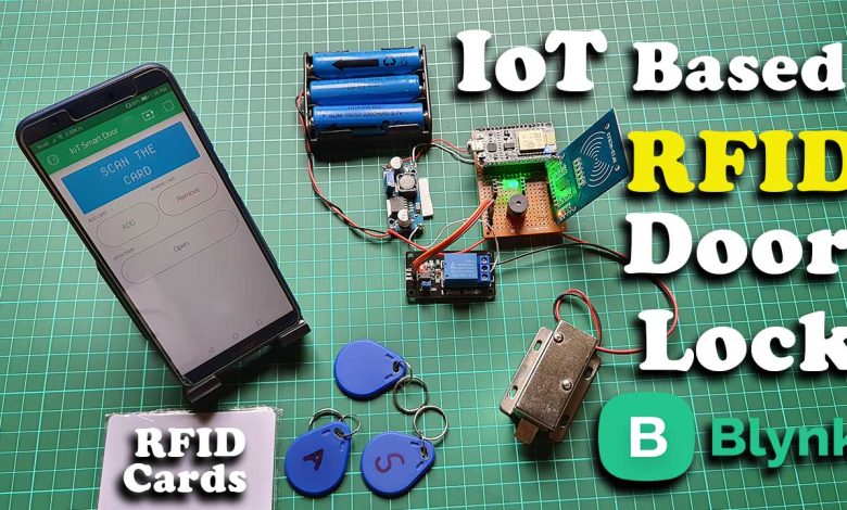
Today in this project you will learn How to make an IoT RFID Door Lock system using NodeMCU ESP8266, RFID MFRC522 Module, a Relay, Solenoid lock, and Blynk IoT platform.
Overview: IoT RFID Door Lock with ESP8266
In a previous project, we made an RFID-based smart iot door lock, where we can remotely monitor and control users. But, we cannot add a new RFID card or change the RFID card without reprogramming the device. So, in this project, we made a system where you can add and remove RFID cards easily. You can save up to 10 RFID Card UID on NodeMCU EEPROM. User RFID UIDs are saved on EEPROM, data won’t get erased even when the device is offline. With the help of this project, you can remotely control your door lock from anywhere in the world using your phone.
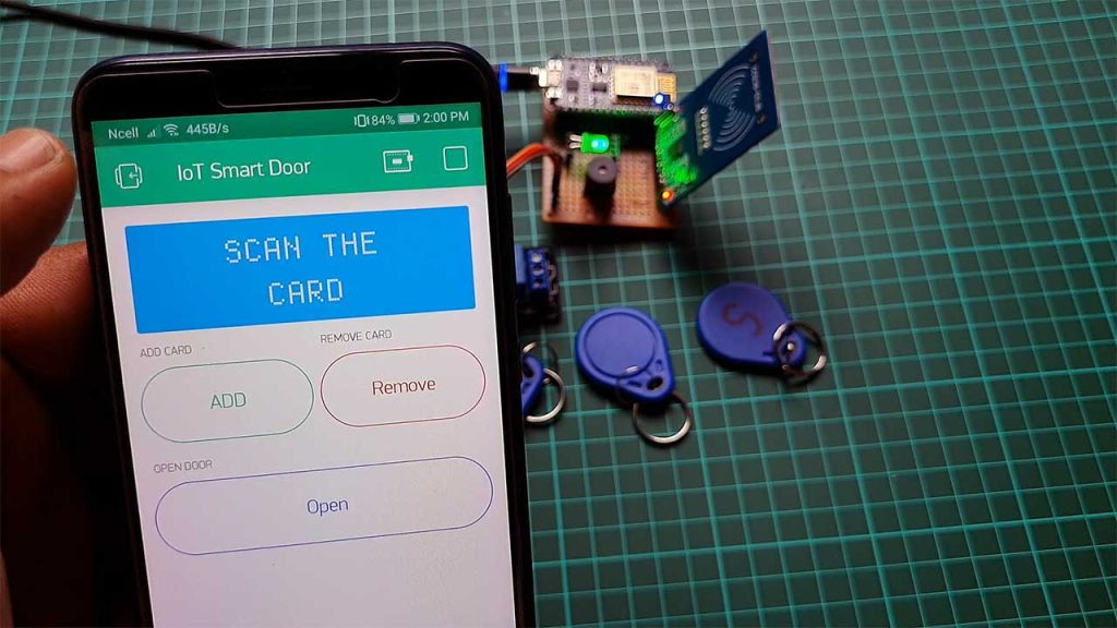
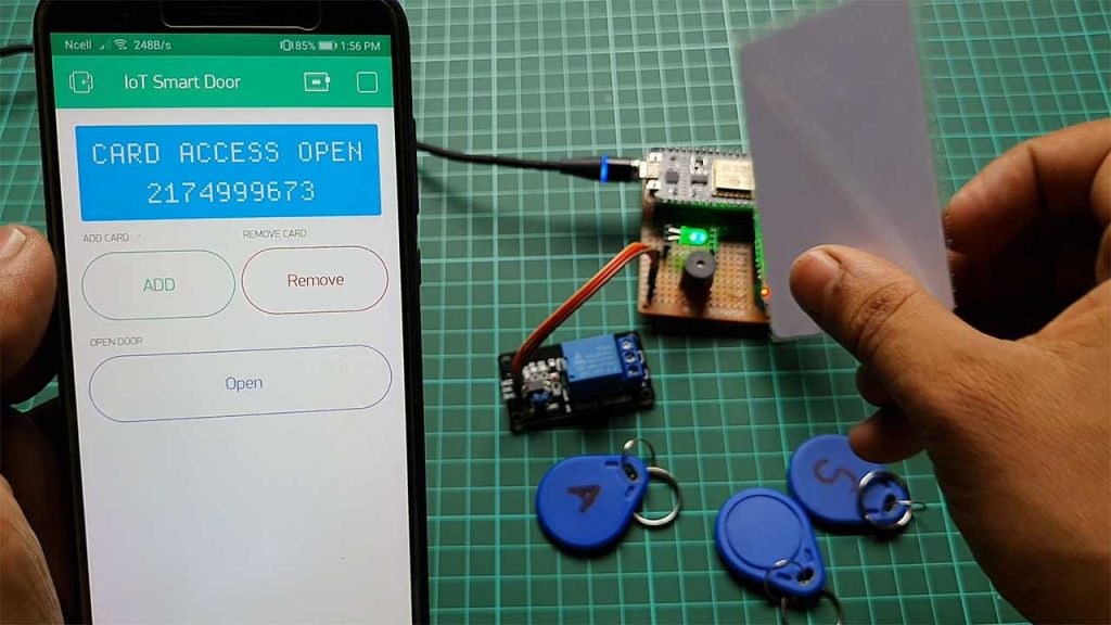
First of all, let’s see the overview of this project. In the Blynk IoT App, I have added an LCD Widget for Displaying Information. And some buttons to control the whole system over the internet. Each time user swipes a card a message is received. There are Add and Remove button which helps to add a new RFID card and remove it if required. Similarly, The Open button helps the admin to unlock the door without having an RFID card.
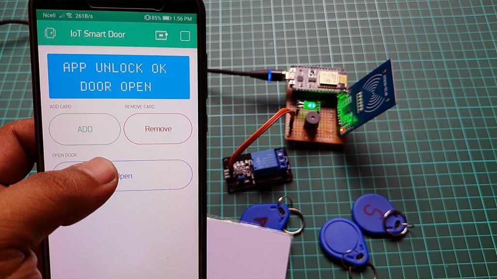
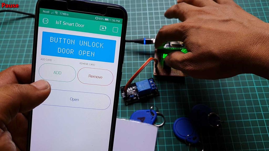
In the hardware part, you can add a push button to the D3 pin of NodeMCU that helps to unlock the door when you are inside the room. For this demonstration, I am using the NodeMCU built-in flash button to open the door lock.
Features of IoT based RFID Smart Door Lock System
- Easily add and remove RFID cards from anywhere in the world.
- Add or Remove RFID Cards without a hardcoding device.
- Easily Open the door lock using a push-button when you are Inside.
- Live Monitor Your Door Lock From anywhere in the world.
- A LED indicator for power.
- Buzzer for an alert system.
- Open the door using a button on the app when you don’t have an RFID card.
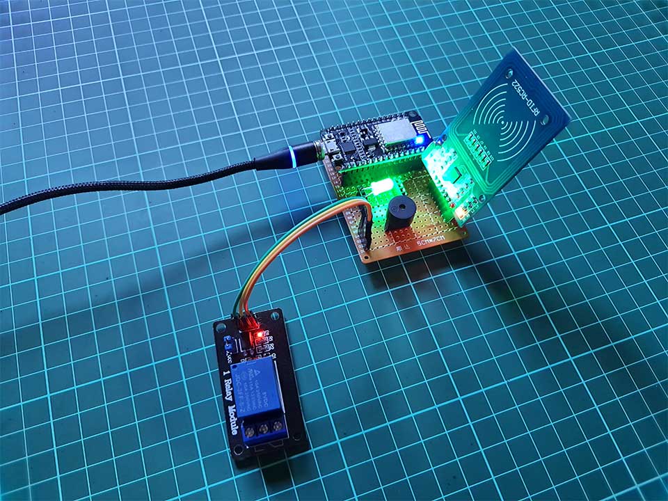
You can also add a LED to indicate WiFi connection and Blynk IoT server connection. It blinks while data is sent successfully to the server. Similarly, a Buzzer produces two different sounds for authorized access and access denied.
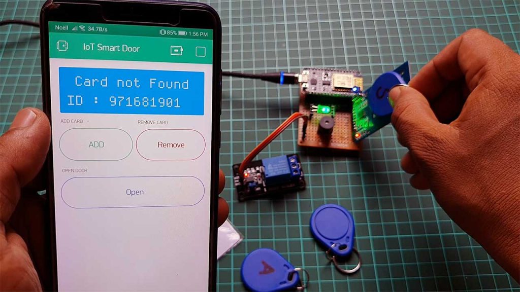
As You can see here, only authorized users can unlock the door lock.
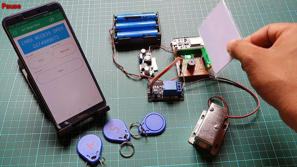
Previous Door Lock Projects:
- RFID Based Solenoid Door Lock with Arduino
- Fingerprint Door Lock System using Arduino and Smartphone
- RFID Master Card Door Lock System using Arduino
- IoT Based RFID Smart Door Lock System Using NodeMCU ESp8266
Components Required
The components and tools used in this project are easily available on Amazon.
| S.N | Components Name | Quantity | |
|---|---|---|---|
| 1 | NodeMCU ESP8266 | 1 | https://amzn.to/3mTuL95 |
| 2 | RFID MFRC-522 Module | 1 | https://amzn.to/3pOPpb4 |
| 3 | 12V Solenoid Door Lock | 1 | https://amzn.to/3NygYTa |
| 4 | Green LED | 1 | https://amzn.to/3JXRSLd |
| 5 | Few jumpers wires | 20 | https://amzn.to/3klh0A4 |
| 6 | 3.7V 18650 Battery | 4 | https://amzn.to/3DnimDm |
| 7 | 3.7V 18650 Battery holder | 1 | https://amzn.to/3LpS7z8 |
| 8 | LM2596 Buck Converter | 1 | https://amzn.to/3ISoXHh |
| 9 | Buzzer | 1 | https://amzn.to/3mJNp4p |
IoT Smart RFID Door Lock Circuit Diagram
As you can see the circuit diagram is very simple to understand.
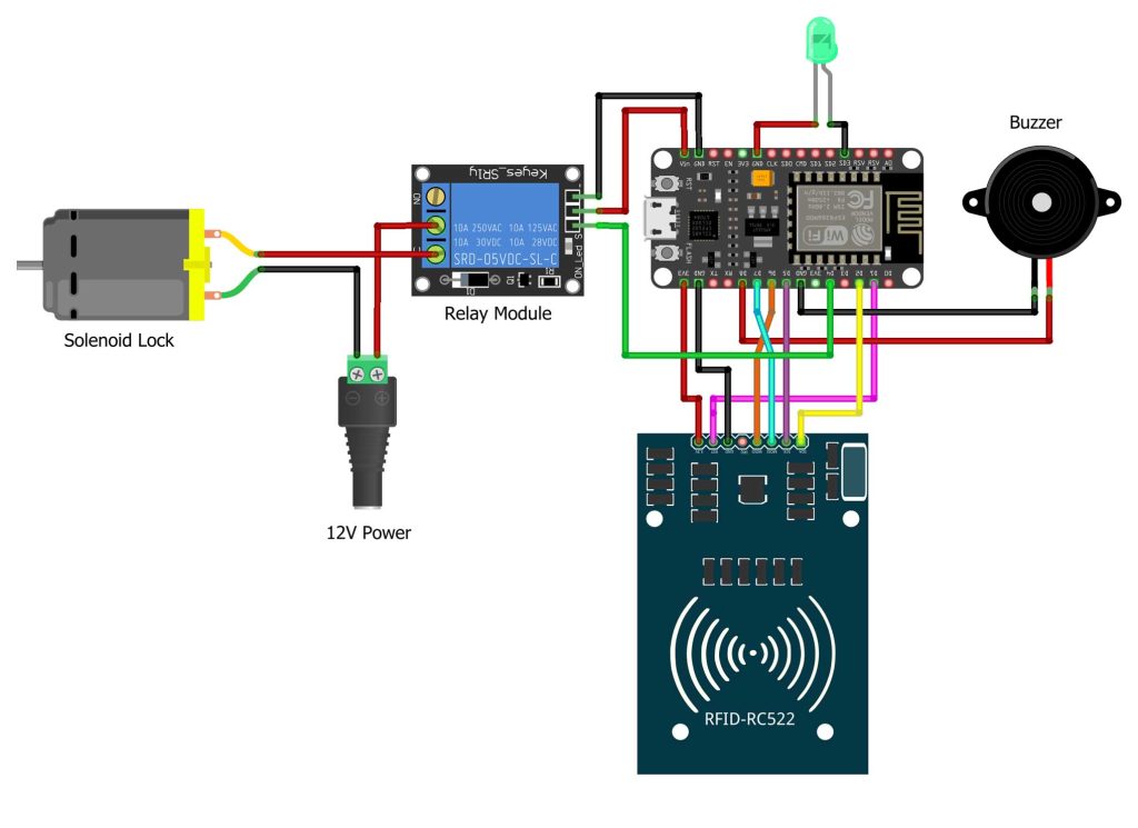
Connect the RFID Module to NodeMCU as per the circuit diagram.
D2 <———-> SDA/SS
D5 <———-> SCK
D7 <———-> MOSI
D6 <———-> MISO
GND <———-> GND
D1 <———-> RST
3V/3V3 <———-> 3.3V
Connect Relay Input Pin to D4 pin of NodeMCU. Similarly, Buzzer Negative Terminal is connected to the Ground and the Positive terminal to the D8 Pin of NodeMCU. Now the Green LED is connected to the SD3(GPIO 10) Pin of NodeMCU.
Project PCB Gerber File & PCB Ordering Online
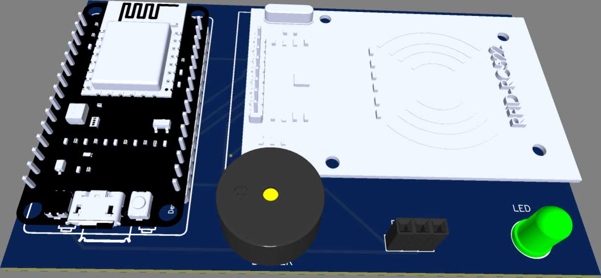
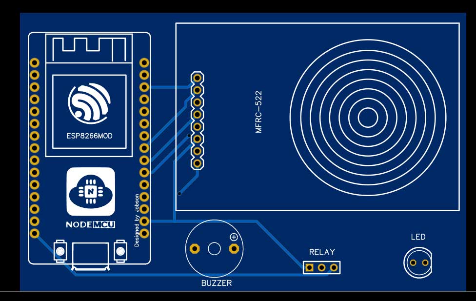
You can simply assemble the circuit on a breadboard. But To remove messy wiring and give a clean look, I designed a PCB prototype for this project. It is also helpful for troubleshooting without any errors. You can download the Gerber file of my PCB Design from the link attached below. The PCB looks like the image shown below.
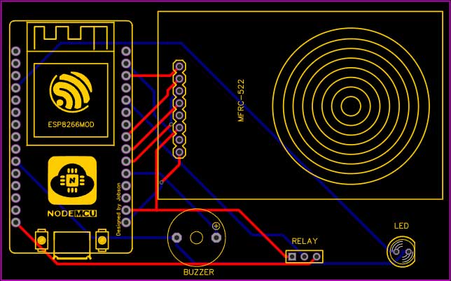
I provided the Gerber File for IoT RFID Door Lock System Using NodeMCU ESP8266 PCB below.
You can simply download the Gerber File and order your custom PCB from PCBWay
Visit the PCBWay official website by clicking here: https://www.PCBWay.com/. Simply upload your Gerber File to the Website and place an order. I prefer PCBWay for ordering custom PCBs. PCBWay is a place that brings manufacturers and customers together. They have more than a decade of experience in this field of fabrication and prototyping and assembling of PCBs. PCBWay has proved its focus on its customers needs in terms of cost-effectiveness, delivery, and quality. And this can be proved by their outstanding customer reviews.
Setting Up Blynk Application
We need to set up the Blynk App to monitor and control door lock using the ESP8266 NodeMCU board. To set up Blynk Application, Download & Install the Application on your smartphone. Available in both Android PlayStore and IOS AppStore. Open the App & create a New Account using your email address.
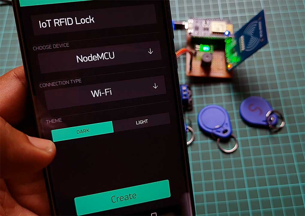
- Click on create a new project
- Provide the Name of your project as “IoT RFID Door Lock”
- Choose NodeMCU Board
- Select connection type as Wi-Fi, then click on Create Button.
- They sent the Blynk authentication token to your email address. (We need it later on programming)
- Now, click on the (+) icon at the top right corner of the screen.
- Search for the “LCD” widget and it to your main screen.
- Also, add 3 Button Widget to the main screen.
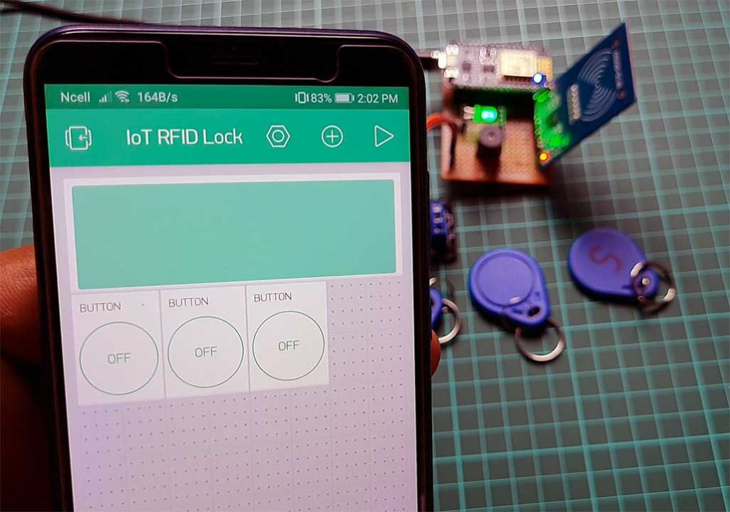
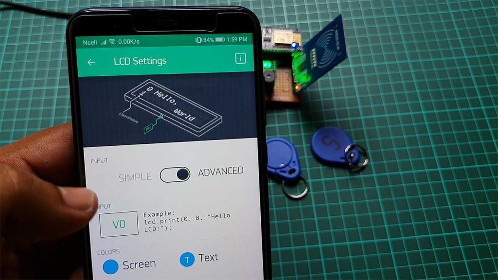
- Click on the LCD Widget and Change Mode to Advanced. Then set the Input Pin to Virtual Pin V0.
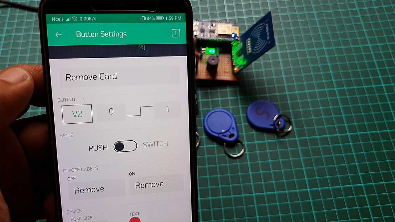
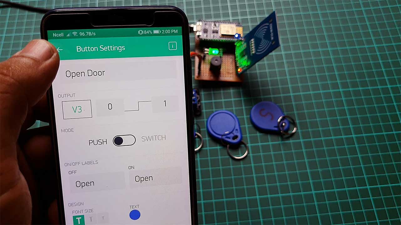
- Now click on the button Widget. Name the Widget as ADD Card
- Set the Input Pin to Virtual Pin V1, Enter the On-Off levels but leave the button mode to push.
- You can set colors and fonts size according to your need.
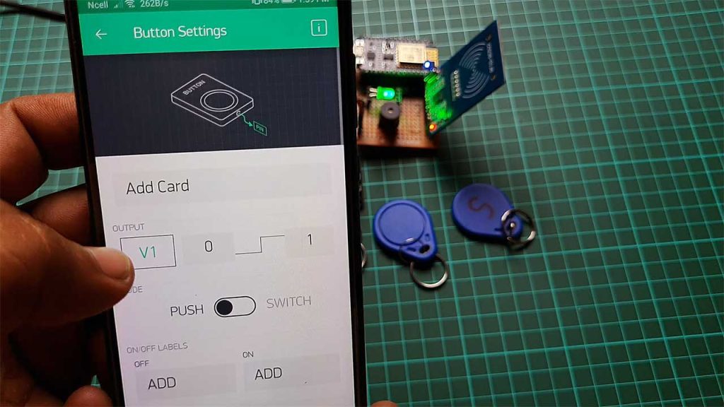
Similarly, do the same for Remove Card, and Open Door with the help of the images below.
Finally, the Blynk App setup for IoT RFID Door Lock using NodeMCU ESP8266 is completed.
Source Code/Program
The Source Code for the ESP8266-based IoT RFID Door Lock System is given below. The code requires MRFC522 library & Blynk Library for compilation. First, download the required libraries and add them to the Arduino IDE.
#define BLYNK_PRINT Serial
#include <ESP8266WiFi.h>
#include <BlynkSimpleEsp8266.h>
#include <SPI.h>
#include <MFRC522.h>
#include <EEPROM.h>
From this code part, change the Wi-Fi SSID, Password & Blynk Authentication Token. Use the same API Token sent to your email address.
char auth[] = "NF_xxx-yyy-zzz_ErFyB";
char ssid[] = "IoT RFID Door Lock";
char pass[] = "RFID@DoorLock";
Final Program Code
This is the final program code for IoT RFID Door Lock using ESP8266 and Blynk IoT Platform. Most of the code is the same and is already explained in my previous projects. Simply copy the code and paste it into your Arduino IDE.
#define BLYNK_PRINT Serial
#include <ESP8266WiFi.h>
#include <BlynkSimpleEsp8266.h>
#include <SPI.h>
#include <MFRC522.h>
#include <EEPROM.h>

#define SS_PIN 4   //D2
#define RST_PIN 5   //D1
#define BTN_PIN 0  //D3
#define SLN_PIN 2  //D4

MFRC522 mfrc522(SS_PIN, RST_PIN);
unsigned long uidDec, uidDecTemp;
int ARRAYindexUIDcard;
int EEPROMstartAddr;
long adminID = 1122539531;
bool beginCard = 0;
bool addCard = 1;
bool skipCard = 0;
int LockSwitch;
unsigned long CardUIDeEPROMread[] = {0, 1, 2, 3, 4, 5, 6, 7, 8, 9};
int PiezoPin = 15;  //D8

char auth[] = "NF_xxx-yyy-zzz_ErFyB";
char ssid[] = "IoT RFID Door Lock";
char pass[] = "RFID@DoorLock";

WidgetLCD lcd(V0);
BlynkTimer timer;


void setup() {
  Serial.begin(115200);
  pinMode(SLN_PIN, OUTPUT); digitalWrite(SLN_PIN, LOW);
  pinMode(BTN_PIN, INPUT_PULLUP);
  pinMode(PiezoPin, OUTPUT);

  SPI.begin();
  mfrc522.PCD_Init();

  Blynk.begin(auth, ssid, pass);
  lcd.clear(); //Use it to clear the LCD Widget
  EEPROM.begin(512);
  DisplayWAiT_CARD();
  EEPROMreadUIDcard();

  digitalWrite(PiezoPin, HIGH), delay(100), digitalWrite(PiezoPin, LOW);

}

void loop() {

  digitalWrite(SLN_PIN, LOW);

  if (digitalRead(BTN_PIN) == LOW) {
    digitalWrite(SLN_PIN, HIGH); //unlock
    lcd.clear();
    lcd.print(0, 0, " BUTTON UNLOCK ");
    lcd.print(0, 1, "   DOOR OPEN   ");
    digitalWrite(PiezoPin, HIGH), delay(200), digitalWrite(PiezoPin, LOW);
    delay(2000);
    DisplayWAiT_CARD();
  }

  if (beginCard == 0) {
    if ( ! mfrc522.PICC_IsNewCardPresent()) {  //Look for new cards.
      Blynk.run();
      return;
    }

    if ( ! mfrc522.PICC_ReadCardSerial()) {  //Select one of the cards.
      Blynk.run();
      return;
    }
  }

  //Read "UID".
  for (byte i = 0; i < mfrc522.uid.size; i++) {
    uidDecTemp = mfrc522.uid.uidByte[i];
    uidDec = uidDec * 256 + uidDecTemp;
  }

  if (beginCard == 1 || LockSwitch > 0)EEPROMwriteUIDcard();  //uidDec == adminID

  if (LockSwitch == 0) {
    //CardUIDeEPROMread.
    for (ARRAYindexUIDcard = 0; ARRAYindexUIDcard <= 9; ARRAYindexUIDcard++) {
      if (CardUIDeEPROMread[ARRAYindexUIDcard] > 0) {
        if (CardUIDeEPROMread[ARRAYindexUIDcard] == uidDec) {
          lcd.clear();
          lcd.print(0, 0, "CARD ACCESS OPEN");
          lcd.print(3, 1, uidDec);
          digitalWrite(SLN_PIN, HIGH); //unlock
          digitalWrite(PiezoPin, HIGH), delay(200), digitalWrite(PiezoPin, LOW);
          delay(2000);
          break;
        }
      }
    }

    if (ARRAYindexUIDcard == 10) {
      lcd.clear();
      lcd.print(0, 0, " Card not Found ");
      lcd.print(0, 1, "                ");
      lcd.print(0, 1, "ID : ");
      lcd.print(5, 1, uidDec);
      for (int i = 0; i <= 2; i++)delay(100), digitalWrite(PiezoPin, HIGH), delay(100), digitalWrite(PiezoPin, LOW);
      digitalWrite(SLN_PIN, LOW);  //lock();
      delay(2000);
    }

    ARRAYindexUIDcard = 0;
    DisplayWAiT_CARD();
  }

  Blynk.run();
  timer.run();
}

BLYNK_WRITE(V1) {
  int a = param.asInt();
  if (a == 1) beginCard = 1; else beginCard = 0;
}

BLYNK_WRITE(V2) {
  int a = param.asInt();
  if (a == 1) {
    skipCard = 1;
    if (EEPROMstartAddr / 5 < 10) EEPROMwriteUIDcard();
  } else {
    skipCard = 0;
  }
}

BLYNK_WRITE(V3) {
  int a = param.asInt();
  if (a == 1) {
    digitalWrite(SLN_PIN, HIGH); //unlock
    lcd.clear();
    lcd.print(0, 0, " APP UNLOCK OK ");
    lcd.print(0, 1, "   DOOR OPEN   ");
    digitalWrite(PiezoPin, HIGH), delay(200), digitalWrite(PiezoPin, LOW);
    delay(2000);
    DisplayWAiT_CARD();
  }
}

void EEPROMwriteUIDcard() {

  if (LockSwitch == 0) {
    lcd.clear();
    lcd.print(0, 0, " START REC CARD ");
    lcd.print(0, 1, "PLEASE SCAN CARDS");
    delay(500);
  }

  if (LockSwitch > 0) {
    if (skipCard == 1) {  //uidDec == adminID
      lcd.clear();
      lcd.print(0, 0, "   Remove RECORD   ");
      lcd.print(0, 1, "                ");
      lcd.print(0, 1, "   label : ");
      lcd.print(11, 1, EEPROMstartAddr / 5);
      EEPROMstartAddr += 5;
      skipCard = 0;
    } else {
      Serial.println("writeCard");
      EEPROM.write(EEPROMstartAddr, uidDec & 0xFF);
      EEPROM.write(EEPROMstartAddr + 1, (uidDec & 0xFF00) >> 8);
      EEPROM.write(EEPROMstartAddr + 2, (uidDec & 0xFF0000) >> 16);
      EEPROM.write(EEPROMstartAddr + 3, (uidDec & 0xFF000000) >> 24);
      EEPROM.commit();
      delay(10);
      lcd.clear();
      lcd.print(0, 1, "                ");
      lcd.print(0, 0, "RECORD OK! IN   ");
      lcd.print(0, 1, "MEMORY : ");
      lcd.print(9, 1, EEPROMstartAddr / 5);
      EEPROMstartAddr += 5;
      delay(500);
    }
  }

  LockSwitch++;

  if (EEPROMstartAddr / 5 == 10) {
    lcd.clear();
    lcd.print(0, 0, "RECORD FINISH");
    delay(2000);
    EEPROMstartAddr = 0;
    uidDec = 0;
    ARRAYindexUIDcard = 0;
    EEPROMreadUIDcard();
  }
}

void EEPROMreadUIDcard() {
  for (int i = 0; i <= 9; i++) {
    byte val = EEPROM.read(EEPROMstartAddr + 3);
    CardUIDeEPROMread[ARRAYindexUIDcard] = (CardUIDeEPROMread[ARRAYindexUIDcard] << 8) | val;
    val = EEPROM.read(EEPROMstartAddr + 2);
    CardUIDeEPROMread[ARRAYindexUIDcard] = (CardUIDeEPROMread[ARRAYindexUIDcard] << 8) | val;
    val = EEPROM.read(EEPROMstartAddr + 1);
    CardUIDeEPROMread[ARRAYindexUIDcard] = (CardUIDeEPROMread[ARRAYindexUIDcard] << 8) | val;
    val = EEPROM.read(EEPROMstartAddr);
    CardUIDeEPROMread[ARRAYindexUIDcard] = (CardUIDeEPROMread[ARRAYindexUIDcard] << 8) | val;

    ARRAYindexUIDcard++;
    EEPROMstartAddr += 5;
  }

  ARRAYindexUIDcard = 0;
  EEPROMstartAddr = 0;
  uidDec = 0;
  LockSwitch = 0;
  DisplayWAiT_CARD();
}

void DisplayWAiT_CARD() {
  lcd.clear();
  lcd.print(0, 0, "    SCAN THE   ");
  lcd.print(0, 1, "      CARD      ");
}
Now choose your NodeMCU 12E board and correct port. Compile the Program sketch and Upload it to the NodeMCU board. When you successfully upload the program to the NodeMCU board. Open the serial monitor to see the project in action.
Conclusion
Finally, we have successfully made an IoT-based RFID Door Lock System using NodeMCU ESP8266, RFID MFRC522 Module, a relay module, a Buzzer, and led. I hope this project was helpful for you. If you have any issues do let me know in the comment section below.

Can I used breadboard instead of pcb? Thanks for feedback
Can I use breadboard instead of pcb cause I cannot afford the pcb board. Please reply. Thanks
Yes you can assemble on breadboard
How can you make sure that there’s no random RFID card that can open the door lock? Please reply. Thanks.
what is LM2596 Buck Converter? where did you put that ? Do I really need to buy that component if I use breadboard?
Cause you didnt add it to the circuit diagram. Thats why im confused where did you attached it.
Only required if you want to power your nodemcu and solenoid lock with same 12V power source. It is used to step down 12V to 5V power supply.
So its not necessary to buy buck converter and instead you can power your nodemcu and solenoid lock with the 12v power ? Am I correct?
No. If you don’t buy buck converter you will need two separate power supply 5V for nodemcu and 12V for solenoid lock. If you connect nodemcu to 12V without buck converter you will burn it.
I have a problem, the rfid stops if the esp8266 is not connected to the internet, how can it work without internet
can I use 5v optocoupler relay module that supports high/low level trigger with dc 5v? or just only Single Channel Relay 1 way relay module 1ch 10A Low level trigger?
You can use any of these
Can you complete the components required please ? Cause I will buy the componets na
how many volts do I need 5v, 12v, 24v, 9v? in relay module
If it’s 5V provide 5V if it’s 12V provide 12V
what do you mean if its 5v provide 5v ? i dont understand.
If i will be using 12v power so the required relay module is 12v right? Correct me if im wrong.
Please I want a code that has a RELAY that is turned off when you connect it with ESP8266
You can change the relay code from High to Low or Low to High
why not use blynk 2.0? can you use blynk2.0? are they the same? help me
how to change to blynk2.0? help me
Hello in the video how many volts of relay module did you use ?
5V
Buenas noches, necesito almacenar 60 tarjetas, se puede?
How do I connect esp8266 to my blynk app? Its just says IoT RFID Door Lock wasn’t online yet ?
Hello can you help me with the blynk app it cannot connect to my nodemcu its just says iot dor lock wasn’t online yet
Hello can you help me with the diagram of the buck converter please?
Where will I put the wires of it? I dont know cause you didn’t indicate it in the circuit diagram
rfid stopped after several hours
excuse me, can I use Blynk IoT version 2.0?
one more thing, why does an error appear
‘DisplayWait_CARD() ;’ was not declared in this scope
‘EEPROMreadUIDcard();’ was not declared in this scope
‘EEPROMwriteUIDcard();’ was not declared in this scope
Hye the remove card function didn’t work. Any idea how to fix this?
Why can’t I delete my registered ID tag when deleting it?